Adding devices to Salto Network
Introducción
You can add the devices listed in this section to the Salto Space Network. Click on the device you want to add to know how to do it:
Ethernet encoders
Encoders are used to read keys, and encode keys with access permission data. They are connected to the system either by a USB, Ethernet connection or serial connection. You can add two types of Ethernet encoders to the system by using the Salto Network screen:
You must specify how encoders connect to the system on the Settings screen. Note that you must assign an IP address to Ethernet encoders by using the Salto Network screen before you select them on the Settings screen.
You can update the firmware of an encoder that is plugged into your local PC using either a USB, Ethernet or serial connection. Firmware updates are available when a new version of the Salto software is downloaded. Your Salto technical support contact may also recommend specific firmware updates if required.
- Encoder options panel
Both types of Salto encoders include a Encoder options panel. The table below shows the options you can select in this panel:
| Option | Descripción |
|---|---|
| Run update reader | This option is used to configure an Ethernet encoder to update user keys automatically when users present their keys to it. If you select this option, the encoder runs continuously but it can only update keys. See Updating keys for more information. It cannot be used to encode keys with access data from the Salto software. |
| Enable beeper | If you select this option, the encoder emits beeps when in use. |
| Enable dongle mode | This option allows you to use the online Ethernet encoder in dongle mode. This mode is used to encrypt the data that is sent over the air or when using a third-party encoder. |
NCoder

To add an Ethernet NCoder, do the following:
Select System > Salto Network. The Salto Network screen is displayed.
Click Add. The Add network device dialog box is displayed.
Select NCoder from the drop-down list.
Click OK. The NCoder information screen is displayed.
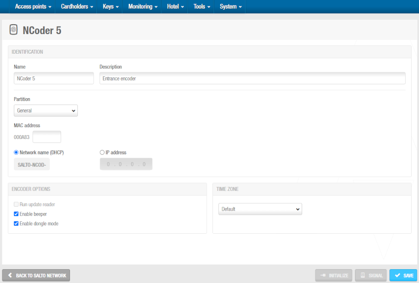 'NCoder' information screen
Type a name for the encoder in the Name field.
Type a description for the encoder in the Description field. For example, it can be used to describe where the encoder is located.
Select the relevant partition from the Partition drop-down list, if required. See Partitions for more information.
Note that the partitions functionality is license-dependent. See Registering and licensing Space for more information.
Type the media access control (MAC) address in the MAC address field. This is displayed on a sticker on the encoder.
Select either the Network name (DHCP) or IP address option.
- If you select the Network name (DHCP) option, this automatically assigns an IP address to the encoder. A Dynamic Host Configuration Protocol (DHCP) server and a DNS are required for this option.
- If you select the IP address option, you must type a static IP address in the field.
Select the Run update reader checkbox if required. See the table on Encoder options panel in Ethernet encoders for more information on this option.
Select the Enable beeper checkbox if required. If you select this option, the encoder emits beeps when in use.
Select the Enable dongle mode checkbox if required. See the table on Encoder options panel in Ethernet encoders for more information on this option.
Select the appropriate time zone from the Time zone drop-down list. Note that the Time zone panel is only displayed if you have enabled the multiple time zones functionality in General options. See Activating multiple time zones and Time zones for more information.
Click Save.
Encoder (Legacy)

To add an Ethernet Encoder (Legacy), do the following:
Select System > Salto Network. The Salto Network screen is displayed.
Click Add. The Add network device dialog box is displayed.
Select Encoder (Legacy) from the drop-down list.
Click OK. The Encoder (Legacy) information screen is displayed.
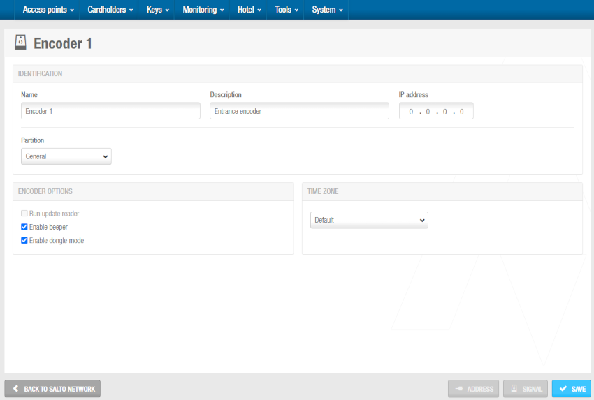 'Encoder (Legacy)' information screen
Type a name for the encoder in the Name field.
Type a description for the encoder in the Description field. For example, it can be used to describe where the encoder is located.
Type an IP address for the encoder in the IP address field.
Select the relevant partition from the Partition drop-down list, if required. See Partitions for more information.
Note that the partitions functionality is license-dependent. See Registering and licensing Space for more information.
Select the Run update reader checkbox if required. See the table on Encoder options panel in Ethernet encoders for more information on this option.
Select the Enable beeper checkbox if required. If you select this option, the encoder emits beeps when in use.
Select the Enable dongle mode checkbox if required. See the table on Encoder options panel in Ethernet encoders for more information on this option.
Select the appropriate time zone from the Time zone drop-down list. Note that the Time zone panel is only displayed if you have enabled the multiple time zones functionality in General options. See Activating multiple time zones and Time zones for more information.
Click Save.
Controllers
Controllers, also known as control units or CUs, are mains-wired hardware devices that can be used to control access where a standalone lock cannot be fitted. For example, on lockers, car park barriers, turnstiles or sliding doors. They allow the management of multiple accesses from a single device. For example, one single controller could control access to both the entrance and exit of a building via a turnstile.
You can add the following controllers:
- CU42E0 (Main)
- CU4200 (Auxiliary)
- CU4EB8 (Expansion Board)
- UBOX4000 (Updater)
- UBOX4000 (Auxiliary)
- GC7 (Gantner)
CU42E0 (Main)
CU42E0 (Main) controllers are CUs that are connected to a local area network (LAN) using a network cable. They connect to the Salto Network using a TCP/IP connection. CU42E0 (Main) controllers can control CU4200 (Auxiliary) controllers. See CU4200 (Auxiliary) section below for more information about these devices.
The CU42E0 (Main) controllers provide a link between the CU4200 (Auxiliary) controllers and Space, and can also transmit data to the auxiliary controllers. This means the CU4200 (Auxiliary) controllers do not require a TCP/IP connection. You must physically connect CU4200 (Auxiliary) controllers to a CU42E0 (Main) controller using an RS485 cable. This establishes communication between the CU4200 (Auxiliary) controllers and the CU42E0 (Main) controller. You must also link CU42E0 (Main) and CU4200 (Auxiliary) controllers in Space so the system can show which main and auxiliary controllers are connected.
CU42E0 (Main) controllers control access to doors by activating their relays. Each CU42E0 (Main) controllers can control a maximum of two doors. They can also update user keys.
Each CU42E0 (Main) controller supports up to 4 CU4200 (Auxiliary) controllers, meaning this that up to 10 online doors can be controlled using a single IP address (1 CU42E0 (Main) controllers + 4 CU4200 (Auxiliary) controllers).
In standalone mode, DIP switches on the CU4200 (Auxiliary) controllers must be set up to 0000, if online, each controller should have its own configured address, using the suitable DIP switch combination in binary format.
See also the CU4200 Controller installation guide for further information about how to install this device.
See the image below for an example.

The maximum distance between the main controller and the last auxiliary controller in line cannot be over 300 meters.
To add a CU42E0 (Main) controller, do the following:
Select System > Salto Network. The Salto Network screen is displayed.
Click Add. The Add network device dialog box is displayed.
Select CU42E0 (Main) from the drop-down list.
Click OK. The CU42E0 (Main) information screen is displayed.
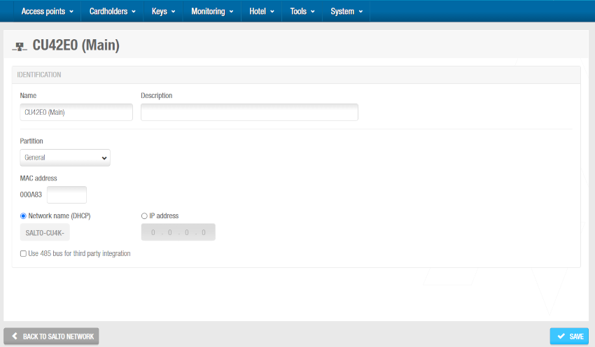 'CU42E0 (Main)' information screen
Type a name for the CU42E0 (Main) controller in the Name field.
Type a description for the CU42E0 (Main) controller in the Description field. For example, it can be used to describe where the CU42E0 (Main) controller is located.
Type the MAC address in the MAC address field. The MAC address is displayed on a sticker on the CU.
Select either the Network name (DHCP) or IP address radio button. If you select the Network name (DHCP) option, this automatically assigns an IP address to the CU42E0 (Main) controller. A DHCP server and a DNS are required for this option. If you select the IP address option, you must type an IP address in the field.
Select Use 485 bus for third party integration when CerPass/Hitachi/OSDP protocol is required to be used with integration with the corresponding third party controller driving RS485 bus. These options imply the use of RS485 bus to integrate with the third party controller, so it is not possible to add additional CU4200 (Auxiliary) controllers in this mode. We can define which readers are sending the received information by CerPass/Hitachi/OSDP. This means a reader can be installed that's not related to a third party integration.
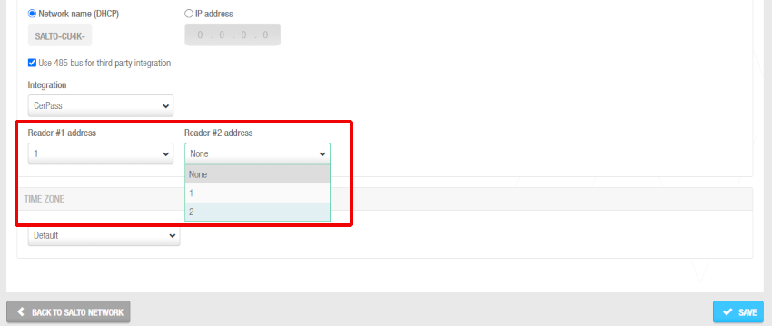 Readers' addresses when sending the received information by CerPass protocol
Select the appropriate time zone from the Time zone drop-down list. Note that the Time zone panel is only displayed if you have enabled the Multiple time zones functionality in Space General options. See Activating multiple time zones and Time zones for more information.
Click Save. The Controllers panel displays on the right side of the screen. From this panel, you can add (+) and delete (-) auxiliary controllers to be connected to this main controller. You can also edit their address (DIP switch) from here by clicking the pencil icon.
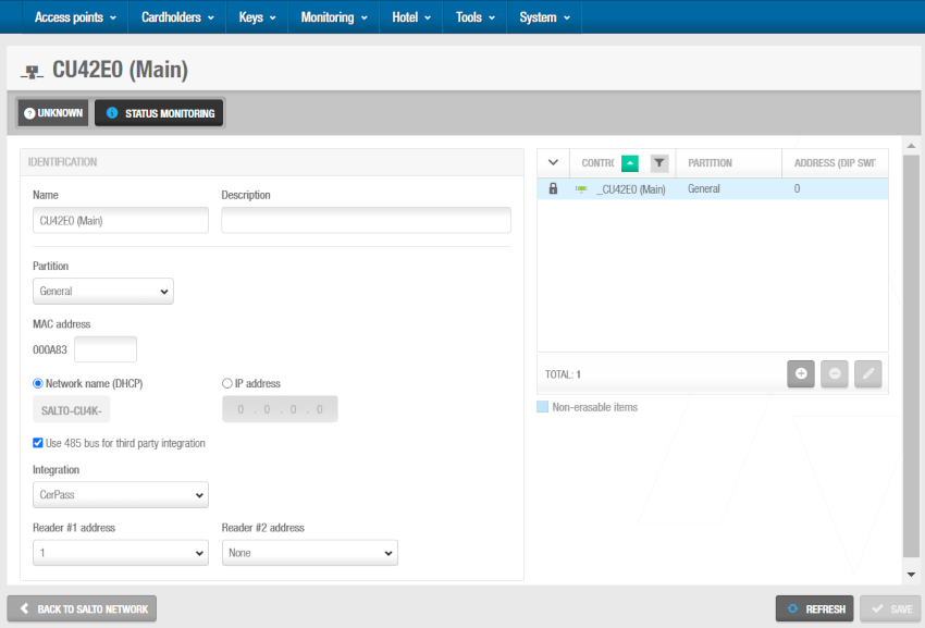 'Controllers' panel - Connecting main and auxiliary controllers
When you click on the add button (+), the Add dialog box is displayed showing a list of CU4200 (Auxiliary) and CU4EB8 (Expansion Board) only if you have already added them to the system. Select the controllers to be added and save the changes. You cannot add controllers that already belong to another main controller. You can also connect auxiliary controllers to main controllers when you add auxiliary controllers to the system.
To enable the delete (-) and edit (pencil icon) buttons, select the auxiliary controller you want to delete/edit.
When you add a CU42E0 (Main) controller, an embedded CU4200 (Auxiliary) controller is automatically created. This one cannot be deleted. Each CU42E0 (Main) controller can support its embedded CU4200 (Auxiliary) controller and a maximum of four other CU4200 (Auxiliary) controllers. The name of the embedded controller will be always the same than the parent CU42E0 (Main) controller preceded by an underscore. For example: _CU42E0.
- Save the changes. The selected CU4200 (Auxiliary) controller is displayed in the Controllers panel.
You can select the CU4200 (Auxiliary) controller and click Edit to change the number in the Address (DIP switch) column if required. See CU4200 (Auxiliary) and CU4EB8 (Expansion Board) for more information about the Address (DIP switch) field. Note that embedded CU4200 (Auxiliary) controllers have a fixed number (0) and this cannot be changed.
- Click on Back to Salto Network to return to the Salto Network screen.
CU4200 (Auxiliary)
CU4200 (Auxiliary) controllers are network connection points that are physically connected to a CU42E0 (Main) controller using an RS485 cable, which establishes communication between the CU4200 (Auxiliary) controllers and the CU42E0 (Main) controller.
The CU4200 (Auxiliary) controllers receive data from the CU42E0 (Main) controller so they do not require a TCP/IP connection. Instead, they communicate with the Salto Network through the CU42E0 (Main) controller to which they are connected.
You must connect CU4200 (Auxiliary) controllers to CU42E0 (Main) controllers in Space. You must also connect CU4200 (Auxiliary) controllers to access points. This means that the system can show which items are connected. Each CU4200 (Auxiliary) controllers can control a maximum of two doors.
You must select Online IP (CU4200) in the Connection type panel on the Door information screen before you can connect an access point to a CU4200 (Auxiliary) controller.
To add a CU4200 (Auxiliary) controller, do the following:
Select System > Salto Network. The Salto Network screen is displayed.
Click Add. The Add network device dialog box is displayed.
Select CU4200 (Auxiliary) from the drop-down list.
Click OK. The CU4200 (Auxiliary) information screen is displayed.
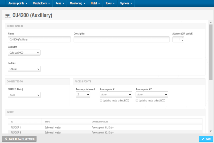 'CU4200 (Auxiliary)' information screen
Type a name for the CU4200 (Auxiliary) controller in the Name field.
Type a description for the CU4200 (Auxiliary) controller in the Description field. For example, it can be used to describe where the CU4200 (Auxiliary) controller is located.
Select the required number by using the up and down arrows in the Address (DIP switch) field. This number corresponds to the switches on the DIP switch panel. You must select a number between 1 and 15. A CU42E0 (Main) controller can support an embedded CU4200 (Auxiliary) controller and a maximum of four other CU4200 (Auxiliary) controllers. Each CU4200 (Auxiliary) controller that you connect to a specific CU42E0 (Main) controller must have a unique number, for example, 1, 2, 3, until 15. Note that the value 0 is used for embedded CU4200 (Auxiliary) controllers. Bear in mind that addresses set up on the controllers should follow the physical DIP switches' configuration on each CU4200 unit.
DIP switch configuration table
| DIP switch | Address (DIP switch) |
|---|---|
| 0000 | Address 0, only for embedded CU4200 controllers |
| 0001 | Address 1 |
| 0010 | Address 2 |
| 0011 | Address 3 |
| 0100 | Address 4 |
| 0101 | Address 5 |
| 0110 | Address 6 |
| 0111 | Address 7 |
| 1000 | Address 8 |
| 1001 | Address 9 |
| 1010 | Address 10 |
| 1011 | Address 11 |
| 1100 | Address 12 |
| 1101 | Address 13 |
| 1110 | Address 14 |
| 1111 | Address 15 |
 CU4200 (Auxiliary) DIP switch example setup
See also the CU4200 Controller installation guide for further information about how to install this device.
Select the appropriate calendar from the drop-down list.
Select the CU42E0 (Main) controller to which you want to connect the CU4200 (Auxiliary) controller from the Connected to drop-down list.
From the Access points panel:
Select the required number from the Access point count drop-down list. You can select either 1 or 2. This defines the number of doors you want the CU4200 (Auxiliary) controller to control. Each CU4200 (Auxiliary) controller can control two readers, what means that it can control either one door that has two readers or two doors where each has one reader. If a door has two readers, one reader controls access from inside to outside, and the other reader controls access from outside to inside. You should select 1 if a door has two readers. If you select 2, an Access point #2 field is displayed on the right-hand side of the Access point #1 field, and you can select an additional door from the drop-down list.
Select the required door from the Access point #1 drop-down list. The access point drop-down lists only display doors if you have already defined some as CU4200 access points. This is done by selecting Online IP (CU4200) in the Connection type panel on the Door information screen. You can also connect online IP (CU4200) doors to CU4200 (Auxiliary) controller in the Connected to field on the Online IP (CU4200) information screen.
Click Save. The Paired CU4EB8 (Expansion Boards) panel displays at the bottom of the CU4200 (Auxiliary) information screen.
From the Paired CU4EB8 (Expansion Boards) panel you can add (+) and delete (-) CU4EB8 controllers to be connected to this CU4200.
When you click on the add button (+), the Add dialog box is displayed showing a list of CU4EB8 (Expansion Board) only if you have already added them to the system. Select the controllers to be added and save the changes. You cannot add CU4EB8 controllers that are already paired with another CU4200 (Auxiliary) controller.
To enable the delete (-) button, select the CU4EB8 controller you want to delete.
- Save the changes and then click on Back to Salto Network to return to the Salto Network screen.
CU4EB8 (Expansion board)
CU4EB8 (Expansion board) controllers are network connection points that are physically connected to a CU42E0 (Main) controller using an RS485 cable, which establishes communication between the CU4EB8 controllers and the CU42E0 (Main) controller.
The CU4EB8 controllers receive data from the CU42E0 (Main) controller so they do not require a TCP/IP connection. Instead, they communicate with the Salto Network through the CU42E0 (Main) controller to which they are connected.
You must connect CU4EB8 controllers to CU42E0 (Main) controllers in Space. In order to add an online C4EB8 into the system it is necessary to create the corresponding CU4EB8 controller in the Salto Network menu.
Select System > Salto Network. The Salto Network screen is displayed.
Click Add. The Add network device dialog box is displayed.
Select CU4EB8 (Expansion board) from the drop-down list.
Click OK. The CU4EB8 (Expansion board) information screen is displayed.
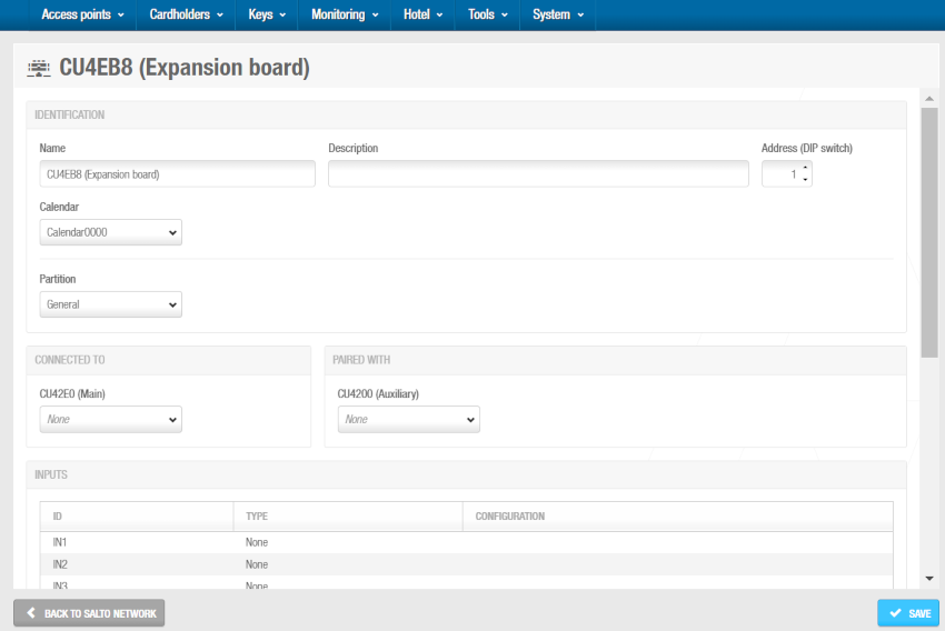 'CU4EB8 (Expansion board)' information screen
Type a name for the CU4EB8 controller in the Name field.
Type a description for the CU4EB8 controller in the Description field. For example, it can be used to describe where the CU4EB8 controller is located.
The position of the CU4EB8 is defined here in the software and also physically on the device (DIP switch). Select the required number by using the up and down arrows in the Address (DIP switch) field. This number corresponds to the switches on the DIP switch panel. You must select a number between 1 and 15. A CU42E0 (Main) controller can support an embedded CU4200 (Auxiliary) controller, a maximum of four other CU4200 (Auxiliary) controllers, and the rest of all the supported devices can be CU4EB8 (Expansion Board) controllers. Each controller that you connect to a specific CU42E0 (Main) controller must have a unique number, for example, 1, 2, 3, until 15. Note that the value 0 is used for embedded CU4200 (Auxiliary) controllers. Bear in mind that addresses set up on the controllers should follow the physical DIP switches' configuration on each CU4200 unit.
DIP switch configuration table
| DIP switch | Address (DIP switch) |
|---|---|
| 0000 | Address 0, only for embedded CU4200 (Auxiliary) controllers |
| 0001 | Address 1 |
| 0010 | Address 2 |
| 0011 | Address 3 |
| 0100 | Address 4 |
| 0101 | Address 5 |
| 0110 | Address 6 |
| 0111 | Address 7 |
| 1000 | Address 8 |
| 1001 | Address 9 |
| 1010 | Address 10 |
| 1011 | Address 11 |
| 1100 | Address 12 |
| 1101 | Address 13 |
| 1110 | Address 14 |
| 1111 | Address 15 |
- Select the CU42E0 (Main) controller to which you want to connect the CU4200 (Auxiliary) controller from the Connected to drop-down list.
- Save the changes and click Back to Salto Network to return to the Salto Network screen.
For further information about how to install this device see the
CU4EB8 (Expansion Board) installation guide.
Using inputs and relays
Inputs
Inputs are the signals or data received by the controller devices. You can setup these inputs in Space so the CU4200 understands how to act. You can set inputs for Reader 1 and Reader 2. You can also set up to 6 inputs for third party devices.
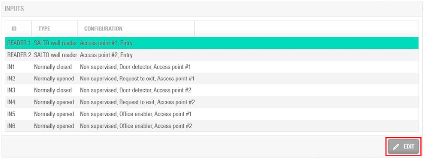 Inputs example configuration
You can set the controller's relays according to the wall reader input. To manage the wall reader input, select the reader and click Edit.
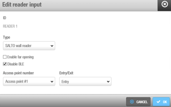 'Edit reader input' option
The Reader input fields are described in the following table:
| Field | Functionality |
|---|---|
| Type | You can select None if no wall reader is connected or Salto wall reader if it is a Salto wall reader. Regardless of this selection, inputs 3, 4 and 5, 6 can still be configured for third party readers if needed. |
| Enable far opening | Allows you to work with wall readers in far opening. By default, in new databases, wall readers will work as near opening. With this flag, you will be able to put the WRs in far opening. In order to have this function available, update the firmware to the latest version. |
| Disable BLE | Allows disabling JustIN Mobile Bluetooth LE keys so they won't be read by the wall reader. |
| Access point number | As the CU4200 can manage up to two different access points, you can decide whether the reader will trigger an opening in access point #1 or #2. See CU4200 (Auxiliary) for more information. |
| Entry/Exit | Select whether the wall reader is an Entry or Exit. |
The CU4200 (Auxiliary) can manage inputs from third party devices. Depending on the signal or on the data arrived to the input, the CU4200 (Auxiliary) can act accordingly. Select the Input ID and click Edit.
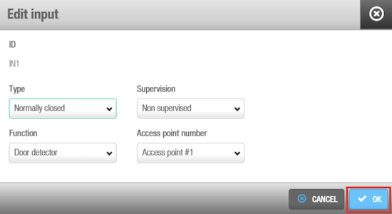 'Edit input' option
The Inputs fields are described in the table below:
Inputs fields: Type
| Field | Functionality |
|---|---|
| Normally opened | Status of the relay in normal position. The relay will be opened in normal position. This type is available for all inputs, from IN1 to IN6 |
| Normally closed | Status of the relay in normal position. The relay will be closed in normal position. This type is available for all inputs, from IN1 to IN6 |
| Third party reader | A third party reader can be used instead of the Salto wall reader. The third party reader requires 2 consecutive inputs, IN3 with IN4 or IN5 with IN6. The third party reader requires an Authorization code that must be entered in the user profile. See Creating users for more information about how to enter an Authorization code in the user profile. |
| CUADAP | The CU4200 can be used to send data from the card to a third party application. Selecting CUADAP the CU will send the cardholder's Wiegang code in a Wiegand interface. The CUADAP requires 2 consecutive inputs, IN3 with IN4 or IN5 with IN6. See Creating Users for more information about how to enter a Wiegand code in the user profile. |
Inputs fields: Supervision
| Field | Functionality |
|---|---|
| Supervision | Select the resistance as required for the supervision. A supervised input is protected against external attacks. |
Inputs fields: Function
| Field | Functionality |
|---|---|
| Function | Select the function you want for the relay. Options include Door detector, Office enabler, Intrusion inhibition, Request to open roller blind, Request to close roller blind, Request to Exit or Request to Entry, Privacy, Block Readers, Alarm Input, Green signal, Red signal, Emergency close, Emergency open. The functions are disabled when type is Third party reader or CUADAP. |
Among these functions: Emergency close and Emergency open are two physical inputs on the controller that allow users to manually trigger a lockdown or an emergency opening directly from the hardware itself. These physical inputs provide the same functionality that can also be managed through the software interface in the Online monitoring > Access points section.
For example, as demonstrated in the below screenshot, a relay in normally opened position could send a request to open a roller blind when presenting a valid key in reader #1 from IN1 and request to close the roller blind from IN2.
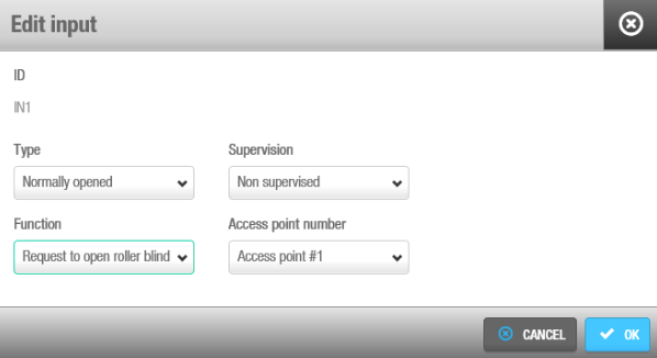 Roller blind example configuration
Non-Salto readers
Non-Salto readers can also be used with CU42xx controllers. There are two separate concepts to understand:
Wall reader configuration: You can set the Edit reader input type to None if you don't want to use one of the two available Salto wall reader inputs. This is useful when you only need one Salto reader instead of two.
Third party reader integration: Independently, you can connect third party readers to inputs 3-6. This works regardless of your Salto wall reader configuration - you can have both Salto readers active, one active, or none active.
This flexible configuration allows for scenarios such as having a Salto wall reader controlling office access while simultaneously using a third party reader (connected to the same controller) for a car park barrier that reads license plates.
The Type field in Edit input shows the Third party reader option in the drop-down menu for IN3 and IN5. Only a Wiegand code is supported. See Configuring Wiegand codes for more information about how to configure the Wiegand format.
An authorization code has to be entered for each user in the Authorization code field on the User profile. See the Users section for more information. Select the Access point from the Access point number drop-down menu and if it will be an Entry or an Exit.
CUADAP
The CU4000 offers the option to configure CUADAP settings directly through Space as the CUADAP module is built inside the node of the CU. However, bear in mind that for CU5000 devices, the settings are configured on the hardware (DIP switch) situated on the controller device itself.
There are three different parameters to be defined on the software to set the CUADAP. These settings can be found on the CU4200 node window: System > Salto Network. See also how to configure CU42E0 (Main) and CU4200 (Auxiliary) devices.
Setting 1
First define the input (3 or 5) under the Type menu to which the third party device will be connected. Automatically the software will assign the following consecutive input for the same purpose, as shown in the below screenshot:
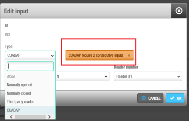 Type selection CUADAP
Setting 2
The second parameter defines the reader (Reader #1, Reader #2, or both) from which the specified data will be provided through the CUADAP to the third party device.
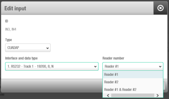 Reader number associated with the CUADAP
Setting 3
The third parameter consists of selecting the interface and data type. Remember that if the data has to be added during the credential encoding (track data and Wiegand) it has to be defined previously in the software. See Creating users on how to configure track data or Wiegand codes for the user.
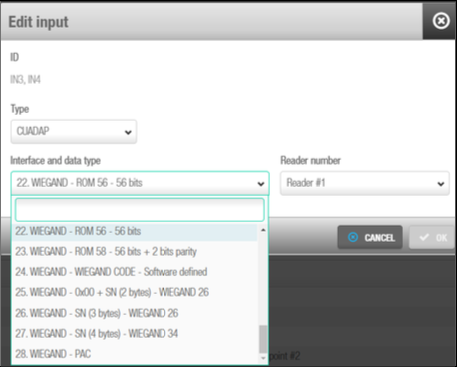 Interface and data type selection
The below table shows the different data, interface and formats available in Space:
| Number | Data | Interface | Format |
|---|---|---|---|
| 1 | Track1 | RS232 (19200-8-N) | (STX, ETX, LRC) |
| 2 | Track2 | RS232 (19200-8-N) | (STX, ETX, LRC) |
| 3 | Track3 | RS232 (19200-8-N) | (STX, ETX, LRC) |
| 4 | % + ROM14 + ? | RS232 (19200-8-N) | RS232 (9600-8-N) |
| 5 | Track1 | RS232 (9600-8-N) | PLAIN |
| 6 | Track2 | RS232 (9600-8-N) | PLAIN |
| 7 | Track3 | RS232 (9600-8-N) | PLAIN |
| 8 | % + ROM14 + ? | RS232 (9600-8-N) | PLAIN |
| 9 | Track 1 | RS232 (19200-8-N) | PLAIN |
| 10 | Track 2 | RS232 (19200-8-N) | PLAIN |
| 11 | Track 3 | RS232 (19200-8-N) | PLAIN |
| 12 | ROM14 | RS232 (19200-8) | PLAIN |
| 13 | Track1 | OMRON | BCD or ALPHA |
| 14 | Track2 | OMRON | BCD or ALPHA |
| 15 | Track2 | OMRON | BCD or ALPHA (no trailing zeros) |
| 16 | Track3 | OMRON | BCD or ALPHA |
| 17 | % + ROM14 + ? | OMRON | ALPHA |
| 18 | Track1 | WIEGAND | BCD or ALPHA |
| 19 | Track2 | WIEGAND | BCD or ALPHA |
| 20 | Track3 | WIEGAND | BCD or ALPHA |
| 21 | % + ROM14 + ? | WIEGAND | ALPHA |
| 22 | ROM | WIEGAND | 56-bit |
| 23 | ROM | WIEGAND | 56-bit + 2 parity bits |
| 24 | WIEGAND-CODE | WIEGAND | Format defined in Space |
| 25 | 0X00+SN(2 bytes) | WIEGAND | Standard 26-bit |
| 26 | SN(3 bytes) | WIEGAND | Standard 26-bit |
| 27 | SN(4bytes) | WIEGAND | 32-bit + 2 parity bits |
Relays
A relay is an electrically operated switch. It is used where it is necessary to control a circuit via a low-power signal. For example, you can use relays to control an electric or magnetic strike, trigger a camera recording or turn an alarm off.
The CU4200 (Auxiliary) has 4 relays that can be configured independently. Select the relay ID and click Edit.
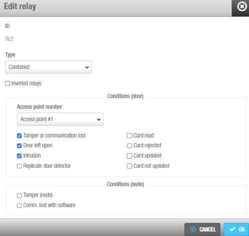 'Edit relay' option
The Edit relay fields are described in the table below:
| Field | Functionality |
|---|---|
| Type | Select the appropriate type as needed. See the relay type fields table below for more info about the different types of modes. |
| Access point number | Select the access point in question. It can be Access point #1, Access point #2 or both. |
| Output | The Output drop-down menu is shown when Output is selected in the Type drop-down menu. Select the output from the drop-down menu. The list of outputs have to be created first in the Outputs list, in the Access points menu. See Access points > Outputs for more information about how to create outputs. The relay will be triggered when a key with a valid output is presented to the wall reader. See the user outputs section for more information about how to add outputs to user access. |
| Inverted relays checkbox | The inverted relays / fail safe option make a specific relay operate in fail safe mode: the relays normally stay on and turn off when activation is required. This feature is based on exchanging the N.C – N.O state of the relay depending on whether the CU is power supplied or not. In this way, the resting state of the CU is different if there is a power supply issue with the device. It's designed for an emergency situation where users would need doors to unlock without electricity. |
The next table describes when relays 1 to 4 will be triggered. If the user access is granted, the relays will trigger according to the following table. Their connection can be Normally Open (NO) or Normally Close (NC).
| Field | Functionality |
|---|---|
| Strike | The relay will be triggered when a valid key is presented. Access point #1, #2, or both can be used. |
| Open roller blind | The relay will be triggered in rotation with Close roller blind relay type to open a roller blind. If a relay is set as Open roller blind, there must be another relay set as Close roller blind. Access point #1, #2 or both can be used. Note: if a door is defined as a roller blind and a relay is set as Strike, the door will work as such in Toggle mode. |
| Close roller blind | The relay will be triggered in rotation with Open roller blind relay type to close a roller blind. If a relay is set as Close roller blind, there must be another relay set as Open roller blind. Access point #1, #2 or both can be used. Note: if a door is defined as a roller blind and a relay is set as Strike, the door will work as such in Toggle mode. |
| Card output | The relay will be triggered when a specific output is in the key access plan. When selecting this type, the Output dropdown menu will be shown so you can chose the output. Access point #1, #2 or both can be used. |
| Timed | The relay will be triggered automatically according with a Timed period. When selecting this type, the Timed period dropdown menu will be shown so you can chose the needed timed period. |
| Timed and Card output | The relay will be triggered automatically according with a timed period or when presenting a valid key, any that comes first. When selecting this type, the Output dropdown menu will be shown so you can chose the output. The Timed period drop-down menu will be also shown so you can chose the needed timed period. Access point #1, #2 or both can be used. |
| Tamper | The relay will be triggered when a wall reader tamper alarm occurs. It occurs when the reader is removed or when it stops communicating with the controller. Access point #1, #2 or both can be used. |
| Door left open | The relay will be triggered when the door is left open. In Access point number, select the access point related with the door position sensor. Access point #1, #2 or both can be used. |
| Intrusion | The relay will be triggered when an intrusion occurs at an access point. Access point #1, #2 or both can be used. |
| Replicate door detector | The relay will be triggered to replicate the door detector alert. This can be used to send a signal to another application when the door was opened. |
| Card read | The relay will be triggered when a card is read. |
| Card rejected | The relay will be triggered when a card is rejected. |
| Card updated | The relay will be triggered when a card is updated. |
| Card not updated | The relay will be triggered when a card is not updated. |
| Combined | The relay will be triggered according to a combination of conditions. For example, as shown in the Edit relay option screenshot above, the relay will be triggered if in Access point #1 the door is left open, if there is an intrusion or if there is a card rejected. Access point #1, #2 or both can be used. |
Controller devices initialization and update
CU42E0 (Main) and CU4200 (Auxiliary) devices are initialized and updated automatically. See the below table for the frequency of each update.
| Automatic process | Check Frequency | Notes |
|---|---|---|
| CU42E0 (Main) doors initialization | 1 minute | Includes initialization + update |
| CU42E0 (Main) doors update | 5 minutes | Can be triggered on request |
| CU4200 (Auxiliary) initialization | 1 minute | Includes initialization + update |
| CCU4200 (Auxiliary) update | 5 minutes | Can be triggered on request |
Even if updates are performed automatically every 5 minutes for the controller devices, a manual update can be performed directly by selecting the device and clicking the Update button in Salto Network.
UBOX4000 (Updater)
They connect to the Salto network using a TCP/IP connection. They connect to the Salto Network using a TCP/IP connection. UBOX4000 updaters functionalities are mainly related to updating tasks and third party integrations. This device also supports an embedded UBOX4000 (Auxiliary).
The UBOX4000 updaters provide a link between the third party unit and Space, and transmit data to the third party unit. This means the third party unit does not require a TCP/IP connection. You must physically connect the third party unit to a UBOX4000 updater using an RS485 cable, which establishes communication between them.
To add a UBOX4000 updater, do the following:
Select System > Salto Network. The Salto Network screen is displayed.
Click Add. The Add network device dialog box is displayed.
Select UBOX4000 (Updater) from the drop-down list.
Click OK. The UBOX4000 (Updater) information screen is displayed.
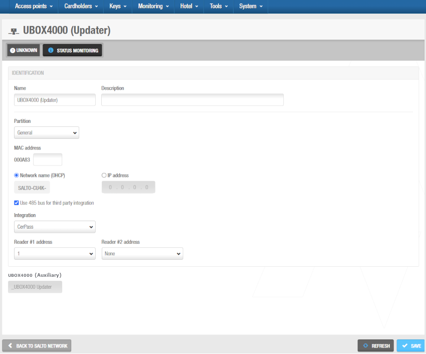 'UBOX4000 (Updater)' information screen
Type a name for the UBOX4000 updater in the Name field.
Type a description for the UBOX4000 updater in the Description field. For example, it can be used to describe where the UBOX4000 updater is located.
Type the MAC address in the MAC address field. The MAC address is displayed on a sticker on the UBOX4000 updater.
Select either the Network name (DHCP) or IP address radio button. A DHCP server and a DNS are required for this option. If you select the IP address option, you must type an IP address in the field. If you select the Network name (DHCP) option, this automatically assigns an IP address to the CU42E0 (Main) controller.
Select Use 485 bus for third party integration when CerPass/OSDP protocol is required to be used with integration with the corresponding third party unit driving RS485 bus. We can define which readers are sending the received information by CerPass/OSDP. This means a reader can be installed that's not related to a third party integration.
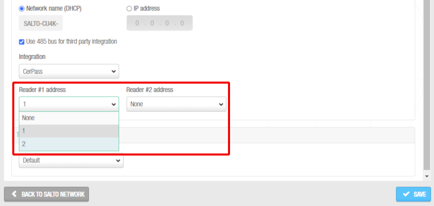 Readers' addresses when sending the received information by CerPass protocol
Select the appropriate time zone from the Time zone drop-down list. Note that the Time zone panel is only displayed if you have enabled the Multiple time zones functionality in Space General options. See Activating multiple time zones and Time zones for more information.
Click Save. The embedded UBOX4000 (Auxiliary) controller displays under the Time zone panel. See UBOX4000 (Auxiliary) controllers for further information.
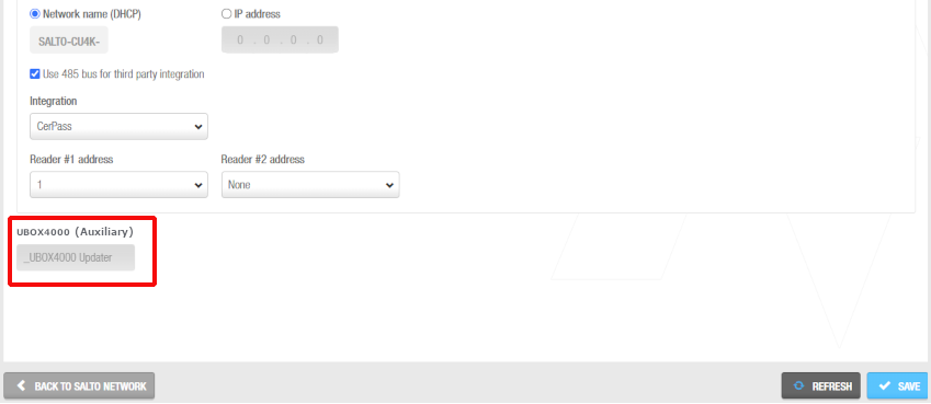 UBOX4000 (Auxiliary)
It cannot be deleted.
When you add a UBOX4000 (Updater) controller, an embedded UBOX4000 (Auxiliary) controller is automatically created. The name of the embedded UBOX4000 (Auxiliary) controller will be always the same as the parent UBOX4000 (Updater) preceded by an underscore. For example: _UBOX4000 updater.
- Click on Back to Salto Network to return to the Salto Network screen.
UBOX4000 (Auxiliary)
UBOX4000 (Auxiliary) controllers are network connection points that are a part of a UBOX4000 (Updater).
You must connect UBOX4000 (Auxiliary) controllers to an access point so that the system can show which items are connected.
When you create a UBOX4000 (Updater), a UBOX4000 embedded (Auxiliary) controller is automatically created. However, you can modify its configuration.
To modify the configuration of the UBOX4000 embedded (Auxiliary) controller, do the following:
Select System > Salto Network. The Salto Network screen is displayed.
Click on the UBOX4000 (Auxiliary) controller to be modified. The UBOX4000 (Auxiliary) information screen is displayed.
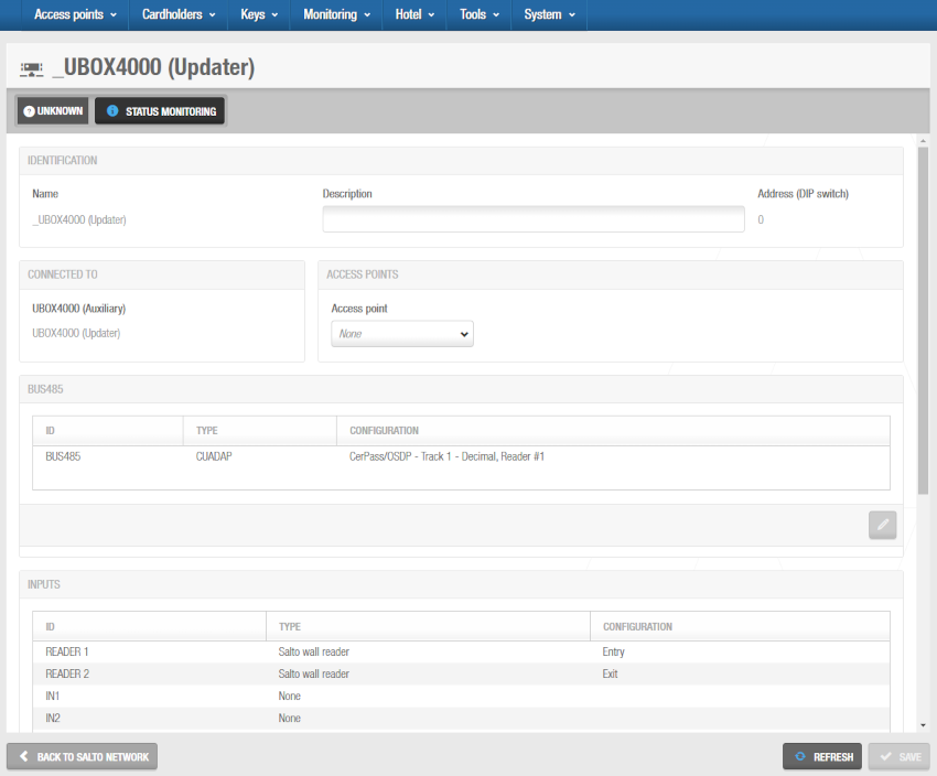 'UBOX4000 (Updater)' information screen
Make the required changes on the Bus485, Relays and Inputs panels by selecting the corresponding bus485/relay/input and clicking on the Edit (pencil icon) button.
Save the changes and then click on Back to Salto Network to return to the Salto Network screen.
GC7 (Gantner)
Earlier versions of Space use the terms "Gantner Controller" and "GAT Net controller" in place of GC7 (Gantner) controllers.
GC7 (Gantner) controllers are mains-wired hardware devices that can be used to control access to online GAT Net lockers. See Connection types for more information on this type of lockers.
To add a GC7 (Gantner) controller, do the following:
Select System > Salto Network. The Salto Network screen is displayed.
Click Add. The Add network device dialog box is displayed.
Select GC7 (Gantner) from the drop-down list.
Click OK. The GC7 (Gantner) information screen is displayed.
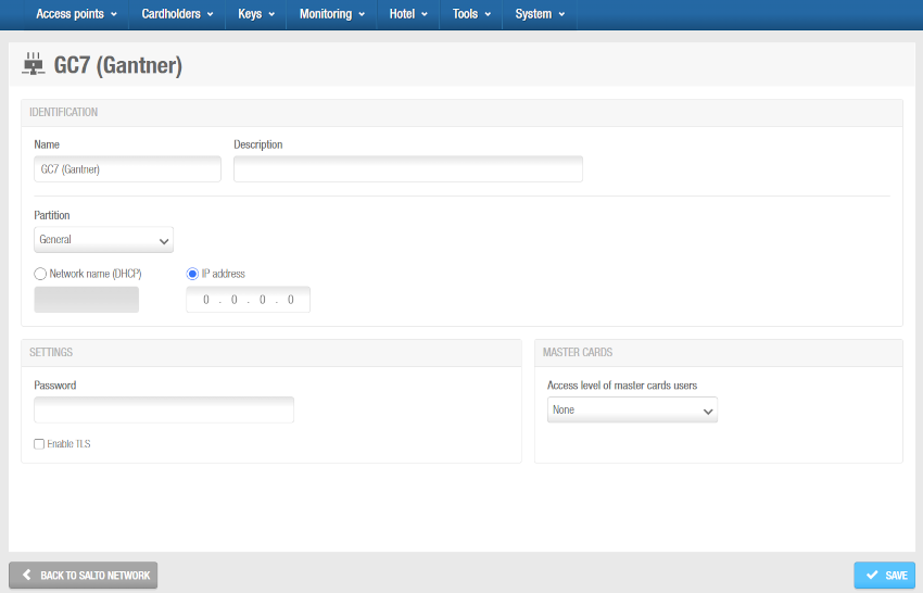 'GC7 (Gantner)' information screen
Type a name for the GC7 (Gantner) controller in the Name field.
Type a description for the GC7 (Gantner) controller in the Description field. For example, it can be used to describe where the GC7 (Gantner) controller is located.
Select the relevant partition from the Partition drop-down list, if required. See Partitions for more information.
Note that the partitions functionality is license-dependent. See Registering and licensing Space for more information.
Select either the Network name (DHCP) or the IP address option. A DHCP server and a DNS are required for this option. If you select the IP address option, you must type an IP address in the field. If you select the Network name (DHCP) option, this automatically assigns an IP address to the GC7 (Gantner) controller.
In the Settings panel, enter the password you have defined while configuring the GC7 controller in the G7 Web Interface and select the Enable TLS checkbox if required. This checkbox enables encrypted communication between the controller and Space. If you select this option, you must configure a certificate in the controller.
Access the Salto Partner area or contact your Salto representative for further information on the GC7 set up for GAT NET.Locks in Space.
- Select the Access level of master cards users from the drop-down list in the Master cards panel. Master cards are a list of cards that can open the locker at any time for maintenance or other purposes. GAT NET.Locks allow master cards to work even if the system is offline (no connection with the host). Those master cards are stored on the GC7 controller with a maximum of 10 cards per controller. Note that there is also another type of master card called the "service master card". This type of master card works if the system is online.
Access the Salto Partner area or contact your Salto representative for further information on GAT Net locks in Space.
As an example of creating a master card list, you should create a user access level and define it as User cards will be GAT Net lockers master cards. Then, you should enable the option Is a GAT Net lockers zone while configuring the GAT Net lockers zone, insert the lockers into this zone and define to what GC7 (Gantner) controllers this access level will be the master. See Zones for more information.
- Save the changes. The Lockers panel displays on the right side of the screen. From this panel, you can add (+) and delete (-) lockers to be connected to this controller. You can also edit their subcontroller values from here by clicking the pencil icon.
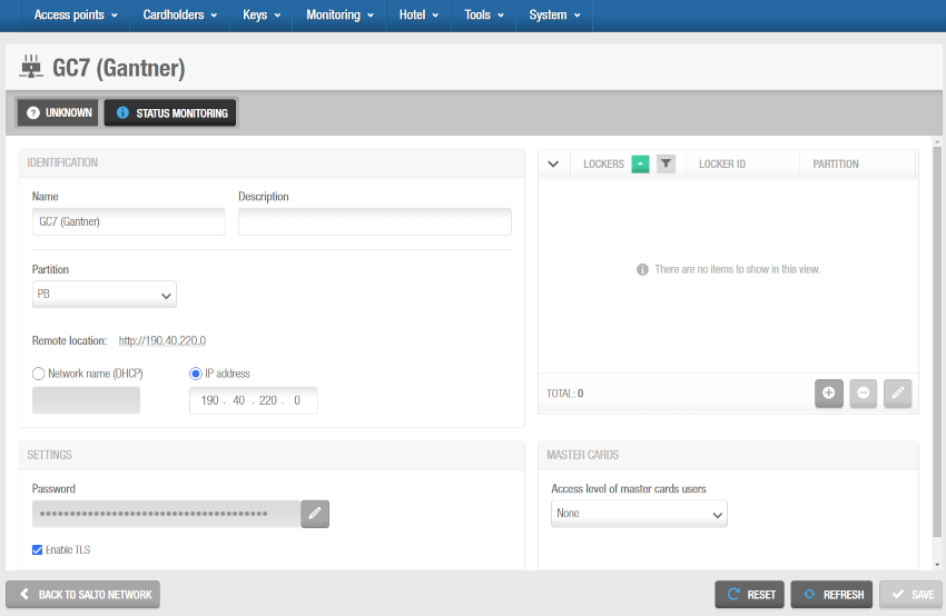 Connecting GC7 (Gantner) controllers and GAT Net lockers
When you click on the add button (+), the Add dialog box is displayed showing a list of GAT Net lockers only if you have already added them to the system. See the lockers section for more information on how to add GAT Net lockers to Space. Select the lockers to be added and save the changes. You cannot add lockers that already belong to another GC7 (Gantner) controller. You can also connect online GAT Net lockers to GC7 (Gantner) controllers when you add lockers to the system.
To enable the delete (-) and edit (pencil icon) buttons, select the locker you want to delete/edit.
- Click on Back to Salto Network to return to the Salto Network screen.
Wireless devices
Gateways are hardware devices that provide a link between networks that use different base protocols. You can add two types of gateways to the system by using the Salto Network screen:
Gateway (RFnet/BLUEnet)
RFnet/BLUEnet gateways allow data to be transmitted back and forth between the system and the Salto wireless locks. RFnet/BLUEnet gateways can be connected to RFnet and BLUEnet nodes. See also the section on RFnet/BLUEnet nodes for more information.
Depending on the lock type, Space manages two different wireless technologies: RFnet and BLUEnet. The Ethernet behavior of the gateway is the same for these two technologies. That's why the gateway setting is the same. What changes is just the internal node (antenna) of the gateway: the antenna could be RFnet or BLUEnet, depending on the type of wireless locks.
You must physically connect RFnet/BLUEnet nodes to a gateway using an RS485 cable to establish communication between the external nodes and the gateway.
You may get more information from the gateway datasheet. If you don't already have that document, contact your Salto partner or tech support team to receive a copy of it.
You must also connect nodes and gateways in Space so the system can show which nodes and gateways are connected.
To add a Gateway (RFnet/BLUEnet), do the following:
Select System > Salto Network. The Salto Network screen is displayed.
Click Add. The Add network device dialog box is displayed.
Select Gateway (RFnet/BLUEnet) from the drop-down list:
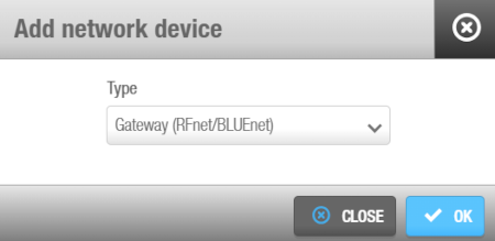 'Add network device' dialog box
Click OK. The Gateway (RFnet/BLUEnet) information screen is displayed.
Type a name for the gateway in the Name field.
Type a description for the gateway in the Description field. For example, it can be used to describe where the gateway is located.
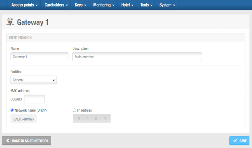 'Gateway (RFnet/BLUEnet)' information screen
Type the media access control (MAC) address in the MAC address field. This is displayed on a sticker on the gateway.
Select either the Network name (DHCP) or IP address option.
- If you select the Network name (DHCP) option, this automatically assigns an IP address to the Gateway (RFnet/BLUEnet). A Dynamic Host Configuration Protocol (DHCP) server and a DNS are required for this option.
- If you select the IP address option, you must type a static IP address in the field.
Note that the Time zone panel is only displayed if you have enabled the Multiple time zones functionality in Space General options. Note that the Time zone panel is only displayed if you have enabled the Multiple time zones functionality in Space General options. See Activating multiple time zones and Time zones for more information.
Click Save. The Nodes panel displays on the right side of the screen. From this panel, you can add (+) and delete (-) nodes to be connected to this gateway.
When you click on the add button (+), the Add dialog box is displayed showing a list of nodes only if you have already added them to the system. Select the nodes to be added and save the changes. You cannot add nodes that already belong to another gateway. You can also connect RFnet and/or BLUEnet nodes to gateways when you add nodes to the system.
To enable the delete (-) button, select the node you want to delete/edit.
- Click Back to Salto Network to return to the Salto Network screen.
The Start Diagnosis option allows to analyze the quality of the wireless communications between a specific Gateway (RFnet/BLUEnet) (and its nodes) and the locks connected to it.
The gateway must have an updated firmware version.
Contact your Salto technical support team for more detailed information about this.
By selecting this option, you can also generate logs for each gateway section.
The logs will be generated as .txt files in the Salto Space logs folder.
Take into account that during this test, the locks under the specific gateway won't be online. Depending on the number of locks, this test can take from 5 minutes to 1 hour and a half. This diagnosis test can be made at the beginning of a wireless system configuration to check the quality or if there is any wireless communication issue in a wireless RFnet or BLUEnet system. You can stop this test by restarting the Space service.
RFnet/BLUEnet nodes
Nodes are network connection points that are physically connected to a gateway using an RS485 cable, which establishes communication between the RF nodes and the RF gateways. In Space you must connect RF nodes to RF gateways, and RF access points to RF nodes, so that the system can show which items are connected. There are 2 types of RF nodes based on the radio platform (RFnet or BLUEnet), and the same gateway could manage both type of nodes at the same time. See Gateway (RFnet/BLUEnet) for more information.
You must select the corresponding online RF option in the Connection type panel on the Door or Room information screen to define a door as an RF access point. See Connection types for non-hotel installations or the hotel connection types section for hotel installations.
To add an RFnet/BLUEnet node, do the following:
Select System > Salto Network. The Salto Network screen is displayed.
Click Add. The Add network device dialog box is displayed.
Select either Node (RFnet) or Node (BLUEnet) from the drop-down list.
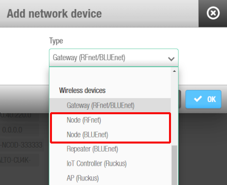 'Add network device' dialog box - 'RF node' drop-down list
- Click OK. The RF node information screen is displayed.
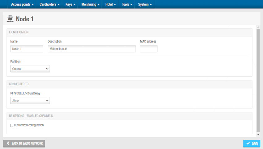 'RF node' information screen
Type a name for the RF node in the Name field.
Type a description for the RF node in the Description field. For example, it can be used to describe where the RF node is located.
Type the MAC address of the antenna in the MAC address field.
Select the relevant partition from the Partition drop-down list, if required. See Partitions for more information.
Note that the partitions functionality is license-dependent. See Registering and licensing Space for more information.
Select the RF gateway to which you want to connect the RF node from the drop-down list in the Connected to panel. The default option is None.
Click Save. The BLUEnet access points or RFnet access points panel is displayed on the right side of the screen. The BLUEnet repeaters panel is also displayed, if applicable.
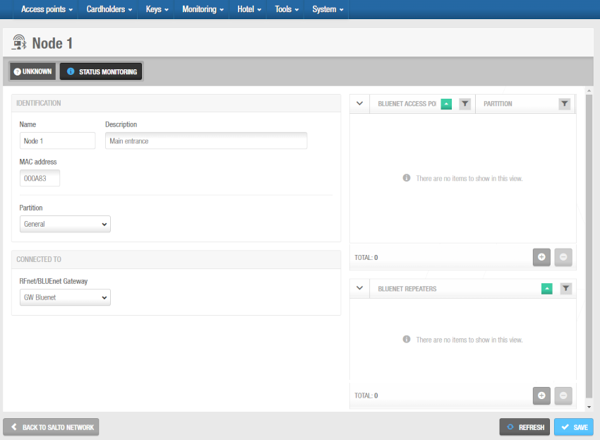 Access points and repeaters panels - 'RF node' information screen
- From the RFnet or BLUEnet Access points panel you can add (+) and delete (-) RF access points to be connected to this RF node.
When you click on the add button (+), the Add dialog box is displayed showing a list of RF access points only if you have already defined doors as RF access points by selecting the corresponding online RF option in the Connection types panel on the Door or Room information screen. Select the access points to be added and save the changes. You can also connect online RF access points to RF nodes when you create an access point. You cannot add RF access points that already belong to another node. See Online RFnet for more information.
To enable the delete (-) button, select the access point you want to delete.
- From the BLUEnet repeaters panel you can add (+) and delete (-) BLUEnet repeaters to be connected to this RF node.
See Online RFnet for more information. Select the repeaters to be added and save the changes. You can also connect BLUEnet repeaters to RF nodes when you add a repeater to the system. You cannot add BLUEnet repeaters that already belong to another node. When you click on the add button (+), the Add dialog box is displayed showing a list of BLUEnet repeaters only if you have already added them to the system.
To enable the delete (-) button, select the repeater you want to delete.
- Click Back to Salto Network to return to the Salto Network screen.
RF gateways have a mini node connected to them. You must add this node in Space by following the procedure for adding RF nodes. Also, you must connect the mini node to the RF gateway in Space.
Repeater (BLUEnet)
BLUEnet repeaters are network connection point devices that are associated to a node or another repeater, and allows the distance between a gateway and an electronic lock to be increased. Based on Salto BLUEnet wireless communication, the Salto BLUEnet repeater does not need to be wired.
To add a BLUEnet repeater, do the following:
Select System > Salto Network. The Salto Network screen is displayed.
Click Add. The Add network device dialog box is displayed.
Select Repeater (BLUEnet) from the drop-down list.
Click OK. The Repeater (BLUEnet) information screen is displayed.
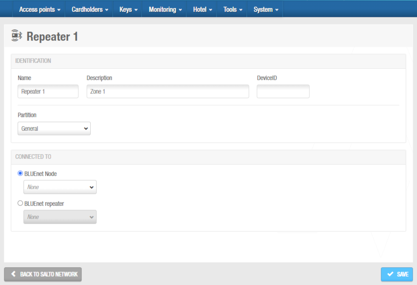 'Repeater (BLUEnet)' information screen
Type a name for the BLUEnet repeater in the Name field.
Type a description for the BLUEnet repeater in the Description field. For example, it can be used to describe where the BLUEnet repeater is located.
Type the device ID in the DeviceID field.
Select the relevant partition from the Partition drop-down list, if required. See Partitions for more information.
Note that the partitions functionality is license-dependent. See Registering and licensing Space for more information.
Select the BLUEnet node or other BLUEnet repeater to which you want to connect the BLUEnet repeater from the drop-down list in the Connected to panel. The default option is None.
Click Save. The BLUEnet access points and BLUEnet repeaters panels are displayed on the right side of the screen.
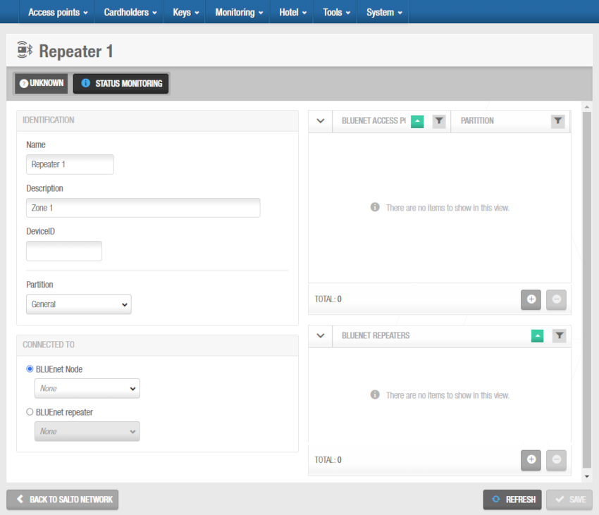 Access points and repeaters panels - 'BLUEnet repeater' information screen
- From the BLUEnet access points panel you can add (+) and delete (-) BLUEnet access points to be connected to this BLUEnet repeater.
When you click on the add button (+), the Add dialog box is displayed showing a list of BLUEnet access points only if you have already defined doors as BLUEnet access points by selecting the corresponding BLUEnet option in the Connection types panel on the Door or Room information screen. Select the access points to be added and save the changes. You can also connect BLUEnet access points to BLUEnet repeaters when you create an access point. You cannot add BLUEnet access points that already belong to another repeater/node.
To enable the delete (-) button, select the access point you want to delete.
- From the BLUEnet repeaters panel you can add (+) and delete (-) BLUEnet repeaters to be connected to this BLUEnet repeaters.
When you click on the add button (+), the Add dialog box is displayed showing a list of BLUEnet repeaters only if you have already added them to the system. Select the repeaters to be added and save the changes. You can also connect BLUEnet repeaters to BLUEnet repeaters. You cannot add BLUEnet repeaters that already belong to another repeater/node.
To enable the delete (-) button, select the repeater you want to delete.
- Click Back to Salto Network to return to the Salto Network screen.

 Atrás
Atrás
