Geräte zum Salto Netzwerk hinzufügen
Überblick
Sie können die folgend aufgeführten Geräte zum Salto Space Netzwerk zufügen. Klicken Sie auf die Geräte, wenn Sie erfahren möchten wie diese zugefügt werden:
Ethernet-Encoders
Encoder werden genutzt, um Medien auszulesen und Zutrittsrechte auf diese zu schreiben. Sie werden entweder über eine USB-, eine serielle oder über eine Ethernet-Verbindung mit dem System verbunden. Sie können im Salto Netzwerk zwei Arten von Ethernet-Encodern zum System zufügen:
Sie müssen in den lokalen Einstellungen festlegen, wie Encoder sich mit dem System verbinden. Beachten Sie, dass Sie Ethernet-Encodern erst im Salto Netzwerk eine IP-Adresse zuweisen müssen, bevor Sie auf diese in den lokalen Einstellungen zugreifen können.
Sie können die Firmware von Encodern, die per USB-, Ethernet- oder serieller Verbindung an Ihren lokalen PC angeschlossen sind aktualisieren. Weitere Informationen finden Sie unter Aktualisieren der Encoder-Firmware. Wenn Sie Ihre Salto-Software aktualisieren, erhalten Sie dabei auch die aktuellste Firmware. Der technische Support von Salto wird bei Bedarf ggfs. auch bestimmte Firmware-Updates empfehlen.
- Abschnitt Encoder-Optionen
Beide Arten von Salto-Encodern verfügen über einen Abschnitt Encoder-Optionen. Die folgende Tabelle zeigt die Optionen, die Sie in diesem Abschnitt auswählen können:
| Medien Optionen | Beschreibung |
|---|---|
| Automatischer Updatemodus aktivieren | In diesem Modus wird der Ethernet-Encoder alle Medien automatisch aktualisieren, die diesem präsentiert werden. Nach Auswahl dieser Option ist der Encoder dauerhaft belegt und kann nur noch Updates durchführen. Er kann in der Salto-Software nicht mehr für die Zuweisung von Medien genutzt werden. Siehe Medien aktualisieren für weitere Informationen. |
| Summer aktivieren | Wenn Sie den Summer aktivieren, erfolgt bei Benutzung des Encoder zusätzlich eine akustische Signalisierung. |
| Aktiviere Dongle-Modus | Mit dieser Option können Sie den Online-Ethernet-Encoder im Dongle-Modus verwenden. Dieser Modus wird verwendet, um die Daten zu verschlüsseln, die drahtlos gesendet werden, bspw. für JustIN-Apps oder wenn ein Drittanbieter-Encoder verwendet wird. |
NCoder

Gehen Sie folgendermaßen vor, um einen Ethernet-NCoder hinzuzufügen:
Gehen Sie auf System > Salto Netzwerk. Das Salto Netzwerk wird angezeigt.
Klicken Sie auf Zufügen. Der Dialog zum Zufügen von Netzwerkgeräten wird angezeigt.
Wählen Sie im Auswahlfeld NCoder aus.
Klicken Sie auf OK. Der Info-Bildschirm NCoder wird angezeigt.
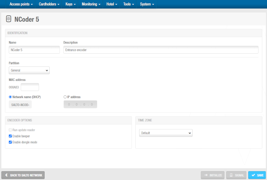 Info-Bildschirm 'NCoder'
Geben Sie dem Encoder im entsprechenden Feld einen Namen.
Geben Sie im Feld Beschreibung eine Beschreibung für den Encoder ein. Dort könnte bspw. der Standort des Encoders vermerkt werden.
Wählen Sie bei Bedarf die passende Partition aus der Liste Partition aus. SiehePartitionen für weitere Informationen.
Beachten Sie, dass die Funktion Partitionen lizenzabhängig sind. Siehe Space registrieren und lizenzieren für weitere Informationen.
Encoder werden genutzt, um Medien auszulesen und Zutrittsrechte auf diese zu schreiben. Dies finden Sie auf einem Aufkleber am Encoder.
Wählen Sie entweder die Option Netzwerkname (DHCP) oder IP-Adresse aus.
- Wenn Sie die Option Netzwerkname (DHCP) wählen, wird dem Encoder automatisch eine IP-Adresse zugewiesen. Für diese Option sind ein Dynamic-Host-Configuration-Protocol-Server(DHCP) und ein DNS erforderlich.
- Wenn Sie die IP-Adresse Option auswählen, müssen Sie eine statische IP-Adresse im Feld eingeben.
Aktiveren Sie bei Bedarf die Funktion Automatischer Updatemodus aktivieren. Weitere Informationen zu dieser Option finden Sie in der Tabelle unter Encoder-Optionen im Feld Ethernet-Encoder.
Aktiveren Sie bei Bedarf die Funktion Summer aktivieren. Wenn Sie den Summer aktivieren, erfolgt bei Benutzung des Encoder zusätzlich eine akustische Signalisierung.
Aktivieren Sie bei Bedarf die Einstellung aktiviere Dongle-Modus. Weitere Informationen zu dieser Option finden Sie in der Tabelle unter Encoder-Optionen im Feld Ethernet-Encoder.
Legen Sie die passende Zeitzone im gleichnamigen Auswahlfeld fest. Das Auswahlfeld Zeitzone wird Ihnen nur angezeigt, wenn Sie in den allgemeinen Optionen die Funktion zur Nutzung mehrerer Zeitzonen aktiviert haben. Siehe Mehrere Zeitzonen verwenden und Zeitzonen für weitere Informationen.
Klicken Sie auf Speichern.
Encoder (Altgerät)

Führen Sie folgende Schritte aus, um einen Encoder (Altgerät) hinzuzufügen:
Gehen Sie auf System > Salto Netzwerk. Das Salto Netzwerk wird angezeigt.
Klicken Sie auf Zufügen. Der Dialog zum Zufügen von Netzwerkgeräten wird angezeigt.
Wählen Sie im Auswahlfeld Encoder (Altgerät) aus.
Klicken Sie auf OK. Der Info-Bildschirm Encoder (Altgerät) wird angezeigt.
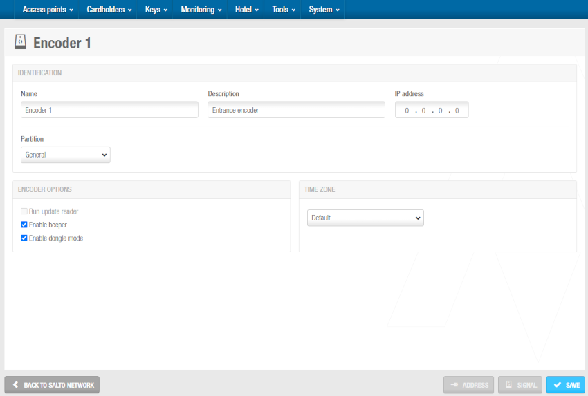 Info-Bildschirm 'Encoder (Altgerät)'
Geben Sie dem Encoder im entsprechenden Feld einen Namen.
Geben Sie im Feld Beschreibung eine Beschreibung für den Encoder ein. Dort könnte bspw. der Standort des Encoders vermerkt werden.
Geben Sie im entsprechenden Feld eine IP-Adresse ein.
Wählen Sie bei Bedarf die passende Partition aus der Liste Partition aus. SiehePartitionen für weitere Informationen.
Beachten Sie, dass die Funktion Partitionen lizenzabhängig sind. Siehe Space registrieren und lizenzieren für weitere Informationen.
Aktiveren Sie bei Bedarf die Funktion Automatischer Updatemodus aktivieren. Weitere Informationen zu dieser Option finden Sie in der Tabelle unter Encoder-Optionen im Feld Ethernet-Encoder.
Aktiveren Sie bei Bedarf die Funktion Summer aktivieren. Wenn Sie den Summer aktivieren, erfolgt bei Benutzung des Encoder zusätzlich eine akustische Signalisierung.
Aktivieren Sie bei Bedarf die Einstellung aktiviere Dongle-Modus. Weitere Informationen zu dieser Option finden Sie in der Tabelle unter Encoder-Optionen im Feld Ethernet-Encoder.
Legen Sie die passende Zeitzone im gleichnamigen Auswahlfeld fest. Das Auswahlfeld Zeitzone wird Ihnen nur angezeigt, wenn Sie in den allgemeinen Optionen die Funktion zur Nutzung mehrerer Zeitzonen aktiviert haben. Siehe Mehrere Zeitzonen verwenden und Zeitzonen für weitere Informationen.
Klicken Sie auf Speichern.
Steuerungen
Steuerungen (auch bekannt als Controller oder CUs) sind netzverdrahtete Hardware-Geräte, mit denen Zutritt dort kontrolliert werden kann, wo batteriebetriebene Türkomponenten nicht eingesetzt werden können. Beispielsweise an Schließfächern, Schranken, Drehkreuzen oder Schiebetüren. Sie ermöglichen die Verwaltung mehrerer Zutrittspunkte von einem Gerät aus. Beispielsweise könnte eine einzelne Steuerung über ein Drehkreuz den Ein- und Ausgang eines Gebäudes regeln.
Die folgenden Steuerungen können zugefügt werden:
- CU42E0 (Main)
- CU4200 (Erweiterung)
- CU4EB8 (Erweiterungs-Board)
- UBOX4000 (Updater)
- UBOX4000 (Erweiterung)
- GC7 (Gantner)
CU42E0 (Main)
CU42E0 (Main)-Steuerungen sind CUs, die über ein Netzwerkkabel mit einem lokalen Netzwerk (LAN) verbunden sind. Sie verbinden sich mit dem Salto Netzwerk über eine TCP/IP-Verbindung. CU42E0 (Main)-Steuerungen können CU4200 (Erweiterung)-Steuerungen steuern. Weitere Informationen zu diesen Geräten finden Sie im Abschnitt CU4200 (Erweiterung) weiter unten.
Die CU42E0 (Main)-Steuerungen stellen eine Verbindung zwischen den CU4200 (Erweiterung)-Steuerungen und dem Space her und übertragen Daten an die Erweiterungssteuerungen. Das bedeutet, dass CU4200 Erweiterungssteuerungen keine TCP/IP-Verbindung benötigen. Sie müssen CU4200 Erweiterungssteuerungen physisch über ein Kabel per RS485-Bus mit CU42E0 (Main) Steuerungen verbinden. Dadurch wird die Kommunikation zwischen den CU4200 Erweiterungs- und der CU42E0 (Main) Steuerung hergestellt. Sie müssen CU42E0 Haupt- und CU4200 Erweiterungssteuerungen auch in Space verknüpfen, damit das System anzeigen kann, welche Haupt- und Erweiterungssteuerungen angeschlossen sind.
CU42E0 Hauptsteuerungen steuern den Zutritt zu Türen durch Aktivieren ihrer Relais. Jede CU42E0 (Main) Steuerung kann maximal zwei Türen steuern. Sie können auch Personenmedien aktualisieren.
Jede CU42E0 (Main) Steuerung unterstützt bis zu 4 CU4200 (Erweiterung) Steuerungen, d. h. es können bis zu 10 Online-Türen mit einer einzigen IP-Adresse gesteuert werden (1 CU42E0 Haupt- + 4 CU4200 Erweiterungssteuerungen).
Im Standalone-Modus müssen die DIP-Schalter an den CU4200 Erweiterungsteuerungen auf 0000 eingestellt werden. Wenn sie online sind, muss jede Steuerung seine eigene konfigurierte Adresse haben, wobei die entsprechende DIP-Schalterkombination im Binärformat verwendet wird.
Weitere Informationen zur Installation dieses Geräts finden Sie in der Montageanleitung CU4200-Steuerung.
Siehe unten stehendes Beispiel-Bild.

Die maximale Entfernung zwischen der Haupt- und der letzten Erweiterungssteuerung eines Strangs darf 300 Meter nicht überschreiten.
Gehen Sie wie folgt vor, um eine CU42E0 (Main) Steuerung hinzuzufügen:
Gehen Sie auf System > Salto Netzwerk. Das Salto Netzwerk wird angezeigt.
Klicken Sie auf Zufügen. Der Dialog zum Zufügen von Netzwerkgeräten wird angezeigt.
Wählen Sie CU42E0 (Main) aus der Dropdown-Liste aus.
Klicken Sie auf OK. Der Informationsbildschirm CU42E0 (Main) wird angezeigt.
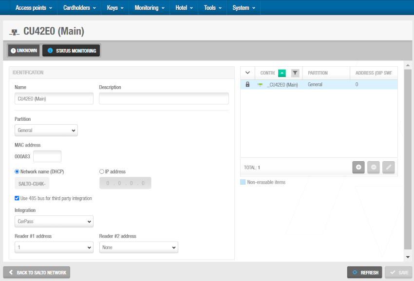
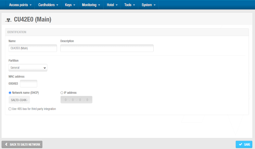 'CU42E0 (Main)' Info-Bildschirm
Geben Sie im Feld Name einen Namen für die CU42E0 (Main) Steuerung ein.
Geben Sie im Feld Beschreibung eine Beschreibung für die CU42E0 (Main) Steuerung ein. Hier können Sie beispielsweise beschreiben, wo sich die CU42E0 (Main) Steuerung befindet.
Geben Sie im Feld MAC-Adresse die MAC-Adresse ein. Die MAC-Adresse finden Sie auf einem Aufkleber auf der CU.
Wählen Sie entweder die Option Netzwerkname(DHCP) oder IP-Adresse aus. Wenn Sie die Option Netzwerkname (DHCP) wählen, wird der CU42E0 (Main) Steuerung automatisch eine IP-Adresse zugewiesen. Für diese Option sind ein DHCP-Server und ein DNS erforderlich. Wenn Sie die IP-Adresse Option auswählen, müssen Sie im entsprechenden Feld eine statische IP-Adresse eingeben.
Aktivieren Sie Benutze 485 Bus für Integration von Drittanbietern, falls eine Integration über das CerPass/Hitachi/OSDP-Protokoll und entsprechende Fremd-Controller mit RS485 benötigt wird. In diesem Modus arbeitet der RS485-Bus ausschließlich mit Fremd-Controllern. Die Anbindung von externen CU4200 Steuerungen ist in diesem Fall nicht möglich. Sie können festlegen, welche Leser die empfangenen Daten von CerPass/Hitachi/OSDP senden. So können auch Leser verwendet werden, die nicht in der Integration genutzt werden sollen.
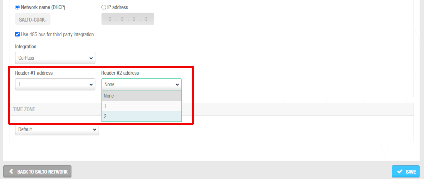 Leseradressen, wenn die empfangenen Daten vom CerPass Protokoll gesendet werden
Legen Sie die passende Zeitzone im gleichnamigen Auswahlfeld fest. Das Auswahlfeld Zeitzone wird Ihnen nur angezeigt, wenn Sie unter System > allgemeine Optionen die Funktion zur Nutzung mehrerer Zeitzonen aktiviert haben. Siehe Mehrere Zeitzonen verwenden und Zeitzonen für weitere Informationen.
Klicken Sie auf Speichern. Der Abschnitt Steuerungen wird auf der rechten Seite des Bildschirms angezeigt. In diesem Abschnitt können Sie Erweiterungssteuerungen hinzufügen (+), die mit dieser Hauptsteuerung verbunden werden sollen, und entfernen (-). Sie können dort auch die Adresse (DIP-Schalter) anpassen, indem Sie auf das Stift-Symbol klicken.
 'Steuerungen'-Abschnitt - Verbinden von Haupt- und Erweiterungssteuerungen
Wenn Sie auf die Schaltfläche Hinzufügen (+) klicken, wird das Dialogfeld Hinzufügen angezeigt. In diesem wird nur dann eine Liste der CU4200 (Erweiterung) und CU4EB8 (Erweiterungs-Board) anzeigt, wenn Sie diese bereits zum System hinzugefügt haben. Wählen Sie die hinzuzufügenden Steuerungen aus und speichern Sie die Änderungen. Sie können keine Steuerungen hinzufügen, die bereits zu einer anderen Hauptsteuerung gehören. Sie können Erweiterungssteuerungen auch mit Hauptsteuerungen verbinden, wenn Sie dem System Erweiterungssteuerungen hinzufügen.
Um die Schaltflächen Löschen (-) und Bearbeiten (Stiftsymbol) zu aktivieren, wählen Sie die Erweiterungssteuerung aus, die Sie löschen oder bearbeiten möchten.
Wenn Sie eine CU42E0 (Main) Steuerung hinzufügen, wird automatisch eine interne CU4200 (Erweiterung) Steuerung erstellt. Diese kann nicht gelöscht werden. Eine CU42E0 (Main) Steuerung unterstützt ihre interne CU4200 (Erweiterung) und maximal vier weitere externe CU4200 (Erweiterung) Steuerungen. Der Name der internen Steuerung entspricht immer dem der übergeordneten CU42E0 (Main) Steuerung, dem ein Unterstrich vorangestellt ist. Zum Beispiel: _CU42E0.
- Speichern Sie die Änderungen. Die ausgewählte CU4200 (Erweiterung) Steuerung wird im Abschnitt Steuerungen angezeigt.
Sie können die CU4200 (Erweiterung) Steuerung auswählen und bei Bedarf auf Bearbeiten klicken, um die Nummer in der Spalte Adresse (DIP-Schalter) zu ändern. Weitere Informationen zum Feld Adresse (DIP-Schalter) finden Sie unter CU4200 (Erweiterung) und CU4EB8 (Erweiterungs-Board). Beachten Sie, dass interne CU4200 (Erweiterung) Steuerungen eine feste Nummer (0) haben, die nicht geändert werden kann.
- Klicken Sie auf Zurück zum Salto Netzwerk, um zum Salto Netzwerk zurückzukehren.
CU4200 (Erweiterung)
CU4200 (Erweiterung) Steuerungen sind Netzwerkverbindungspunkte, die über ein Kabel und RS485-Bus physisch mit einer CU42E0 (Main) Steuerung verbunden sind. Dadurch wird die Kommunikation zwischen den CU4200 (Erweiterung) Steuerungen und der CU42E0 (Main) Steuerung hergestellt.
Die CU4200 (Erweiterung) Steuerungen empfangen Daten von der CU42E0 (Main) Steuerung, sodass sie keine TCP/IP-Verbindung benötigen. Stattdessen kommunizieren sie mit dem Salto Netzwerk über die CU42E0 (Main)-Steuerung, mit der sie verbunden sind.
Sie müssen CU4200 (Erweiterung) Steuerungen in Space mit CU42E0 (Main) Steuerungen verbinden. Sie müssen CU4200 (Erweiterung) Steuerungen auch mit Zutrittspunkten verbinden. Dadurch kann das System die verbundenen Geräte anzeigen. Jede CU4200 (Erweiterung) Steuerung kann maximal zwei Türen steuern.
Sie müssen im Bereich Verbindungstyp auf dem Informationsbildschirm Tür die Option Online-IP (CU4200) auswählen, bevor Sie einen Zutrittspunkt mit einer CU4200 (Erweiterung) Steuerung verbinden können.
Gehen Sie wie folgt vor, um eine CU4200 (Erweiterung) Steuerung hinzuzufügen:
Gehen Sie auf System > Salto Netzwerk. Das Salto Netzwerk wird angezeigt.
Klicken Sie auf Zufügen. Der Dialog zum Zufügen von Netzwerkgeräten wird angezeigt.
Wählen Sie CU4200 (Erweiterung) aus der Dropdown-Liste aus.
Klicken Sie auf OK. Der Informationsbildschirm CU4200 (Erweiterung) wird angezeigt.
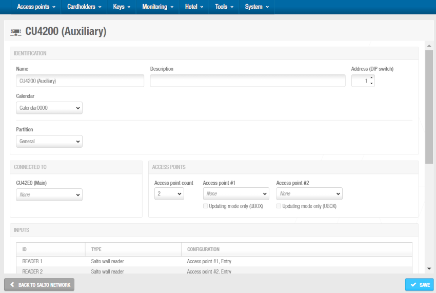 'CU4200 (Erweiterung)' Info-Bildschirm
Geben Sie im Feld Name einen Namen für die CU4200 (Erweiterung) Steuerung ein.
Geben Sie im Feld Beschreibung eine Beschreibung für die CU4200 (Erweiterung) Steuerung ein. So können Sie beispielsweise beschreiben, wo sich die CU4200 (Erweiterung) Steuerung befindet.
Wählen Sie die gewünschte Adresse mithilfe der Auf- und Abwärtspfeile im Feld Adresse (DIP-Schalter) aus. Diese Adresse entspricht den Einstellungen der DIP-Schalter auf der Hardware. Sie müssen eine Zahl zwischen 1 und 15 auswählen. Eine CU42E0 (Main) Steuerung unterstützt ihre interne CU4200 (Erweiterung) und maximal vier weitere externe CU4200 (Erweiterung) Steuerungen. Jede CU4200 (Erweiterung) Steuerung, die Sie mit einer bestimmten CU42E0 (Main) Steuerung verbinden, muss über eine eindeutige Nummer verfügen, z. B. 1, 2, 3, bis 15. Beachten Sie, dass der Wert 0 für interne CU4200 (Erweiterung) Steuerungen verwendet wird. Beachten Sie, dass die auf den Steuerungen eingerichteten Adressen der Konfiguration der physischen DIP-Schalter an jeder CU4200-Einheit entsprechen sollten.
DIP-Schalter Konfigurationstabelle
| DIP-Schalter | Adresse (DIP-Schalter) |
|---|---|
| 0000 | Adresse 0, nur für interne CU4200-Steuerungen |
| 0001 | Adresse 1 |
| 0010 | Adresse 2 |
| 0011 | Adresse 3 |
| 0100 | Adresse 4 |
| 0101 | Adresse 5 |
| 0110 | Adresse 6 |
| 0111 | Adresse 7 |
| 1000 | Adresse 8 |
| 1001 | Adresse 9 |
| 1010 | Adresse 10 |
| 1011 | Adresse 11 |
| 1100 | Adresse 12 |
| 1101 | Adresse 13 |
| 1110 | Adresse 14 |
| 1111 | Adresse 15 |
 CU4200 (Erweiterung) Beispiel für DIP-Schalter-Einstellungen
Weitere Informationen zur Installation dieses Geräts finden Sie in der Montageanleitung CU4200-Steuerung.
Legen Sie im entsprechenden Auswahlfeld den passenden Kalender fest.
Wählen Sie in der Dropdown-Liste Verbunden mit die CU42E0 (Main) Steuerung aus, mit der Sie die CU4200 (Erweiterung) Steuerung verbinden möchten.
Im Abschnitt Zutrittspunkte:
Legen Sie den passenden Wert im Feld Anzahl der Zutrittspunkte fest. Sie können 1 oder 2 wählen. Hiermit legen Sie die Anzahl der Türen fest, die von der CU4200 (Erweiterung) Steuerung gesteuert werden sollen. Jede CU4200 (Erweiterung) Steuerung kann zwei Leser steuern, d. h. sie kann entweder eine Tür mit zwei Lesern oder zwei Türen mit jeweils einem Leser steuern. Wenn eine Tür über zwei Leser verfügt, steuert i. d. R. einer den Zutritt von außen nach innen und einer den Zutritt von innen nach außen. Bei Verwendung einer Tür mit zwei Lesern, müssen Sie 1 auswählen. Wenn Sie zwei auswählen, wird rechts vom Auswahlfeld Zutrittspunkt #1 das Feld Zutrittspunkt #2 eingeblendet, indem Sie einen zweiten Zutrittspunkt konfigurieren können.
Legen Sie im entsprechenden Feld den Zutrittspunkt #1 fest. In diesem Auswahlfeld werden nur Zutrittspunkte angezeigt, die Sie für die Nutzung an einer CU42xx konfiguriert haben. Dies erreichen Sie, indem Sie im Info-Fenster des Zutrittspunkts, im Abschnitt Verbindungstyp Online IP(CU42xx) auswählen. Sie können Online-IP (CU4200) Türen auch mit der CU4200 (Erweiterung) Steuerung im Feld Verbunden mit auf dem Informationsbildschirm Online-IP (CU4200) verbinden.
Klicken Sie auf Speichern. Unten im Info-Fenster der CU4200 (Erweiterung) finden Sie den Abschnitt gekoppelte CU4EB8 (Erweiterungs-Boards).
Im Abschnitt gekoppelte CU4EB8 (Erweiterungs-Boards) können Sie CU4EB8-Steuerungen, die mit dieser CU4200 verbunden werden sollen, hinzufügen (+) und löschen (-).
Wenn Sie auf die Schaltfläche Hinzufügen (+) klicken, wird das Dialogfeld Hinzufügen angezeigt. Darin wird nur dann eine Liste der CU4EB8 (Erweiterungs-Boards) angezeigt, wenn Sie diese bereits dem System hinzugefügt haben. Wählen Sie die hinzuzufügenden Steuerungen aus und speichern Sie die Änderungen. Sie können keine CU4EB8-Steuerungen hinzufügen, die bereits mit einer anderen CU4200 (Erweiterungssteuerung) gekoppelt sind.
Um die Schaltfläche Löschen (-) zu aktivieren, wählen Sie die CU4EB8-Steuerung aus, die Sie löschen möchten.
- Speichern Sie und klicken Sie auf Zurück zum Salto Netzwerk um zum Salto Netzwerk zurückzukehren.
CU4EB8 (Erweiterungs-Board)
CU4EB8 (Erweiterungs-Board)-Steuerungen sind Netzwerkverbindungspunkte, die über ein RS485-Kabel physisch mit einer CU42E0 (Main)-Steuerung verbunden sind, wodurch die Kommunikation zwischen den CU4EB8-Steuerungen und der CU42E0 (Main)-Steuerung hergestellt wird.
Die CU4EB8-Steuerungen erhalten Daten von der CU42E0 (Main)-Steuerung, sodass sie keine TCP/IP-Verbindung benötigen. Stattdessen kommunizieren sie mit dem Salto Netzwerk über die CU42E0 (Main)-Steuerung, mit der sie verbunden sind.
Sie müssen CU4EB8-Steuerungen in Space mit CU42E0 (Main)-Steuerungen verbinden. Um eine Online-CU4EB8 zum System hinzuzufügen, muss im Menü Salto Netzwerk die entsprechende CU4EB8-Steuerung erstellt werden.
Gehen Sie auf System > Salto Netzwerk. Das Salto Netzwerk wird angezeigt.
Klicken Sie auf Zufügen. Der Dialog zum Zufügen von Netzwerkgeräten wird angezeigt.
Wählen Sie in der Dropdown-Liste den Eintrag CU4EB8 (Erweiterungs-Board) aus.
Klicken Sie auf OK. Das Informationsfenster CU4EB8 (Erweiterungs-Board) wird angezeigt.
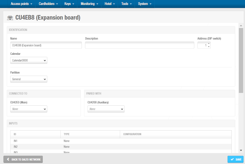 'CU4EB8 (Erweiterungs-Board)' Info-Fenster
Geben Sie im Feld Name einen Namen für die CU4EB8-Steuerung ein.
Geben Sie im Feld Beschreibung eine Beschreibung für die CU4EB8-Steuerung ein. So können Sie beispielsweise beschreiben, wo sich die CU4EB8-Steuerung befindet.
Die Position des CU4EB8 wird hier in der Software und auch physisch am Gerät (DIP-Schalter) festgelegt. Wählen Sie die gewünschte Adresse mithilfe der Aufwärts- und Abwärtspfeile im Feld Adresse (DIP-Schalter) aus. Diese Adresse entspricht den DIP-Schaltereinstellungen auf dem Node. Sie müssen eine Zahl zwischen 1 und 15 auswählen. Eine CU42E0 (Main)-Steuerung kann eine interne CU4200 (Erweiterung)-Steuerung, maximal vier weitere CU4200 (Erweiterung)-Steuerungen und alle übrigen unterstützten Geräte als CU4EB8 (Erweiterungs-Board)-Steuerungen unterstützen. Jeder Controller, den Sie mit einem bestimmten CU42E0 (Haupt)-Controller verbinden, muss eine eindeutige Nummer haben, z. B. 1, 2, 3 bis 15. Beachten Sie, dass der Wert 0 für interne CU4200 (Erweiterung) Steuerungen verwendet wird. Beachten Sie, dass die auf den Steuerungen eingerichteten Adressen der Konfiguration der physischen DIP-Schalter an jeder CU4200-Einheit entsprechen sollten.
DIP-Schalter Konfigurationstabelle
| DIP-Schalter | Adresse (DIP-Schalter) |
|---|---|
| 0000 | Adresse 0, nur für interne CU4200 (Erweiterung)-Steuerungen |
| 0001 | Adresse 1 |
| 0010 | Adresse 2 |
| 0011 | Adresse 3 |
| 0100 | Adresse 4 |
| 0101 | Adresse 5 |
| 0110 | Adresse 6 |
| 0111 | Adresse 7 |
| 1000 | Adresse 8 |
| 1001 | Adresse 9 |
| 1010 | Adresse 10 |
| 1011 | Adresse 11 |
| 1100 | Adresse 12 |
| 1101 | Adresse 13 |
| 1110 | Adresse 14 |
| 1111 | Adresse 15 |
- Wählen Sie in der Dropdown-Liste Verbunden mit die CU42E0 (Main)-Steuerung aus, mit der Sie die CU4200 (Erweiterung)-Steuerung verbinden möchten.
- Speichern Sie und klicken Sie auf Zurück zum Salto Netzwerk um zum Salto Netzwerk zurückzukehren.
Weitere Informationen zur Installation dieses Geräts finden Sie in der
Montageanleitung CU4EB8 (Erweiterungs-Board).
Verwenden von Eingängen und Relais
Eingänge
Eingänge sind die Signale oder Daten, die von Steuerungen empfangen werden. Sie können Eingänge in Space einrichten, damit CU4200 verstehen, wie sie sich verhalten sollen. Sie können Eingänge für Leser 1 und Leser 2 festlegen. Sie können auch bis zu 6 Eingänge für Geräte von Fremdanbietern einrichten.
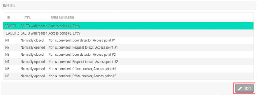 Beispiel für Konfiguration von Eingängen
You can set the controller's relays according to the wall reader input. Um den Eingang des Wandlesers zu verwalten, wählen Sie den Leser aus und klicken Sie auf Bearbeiten.
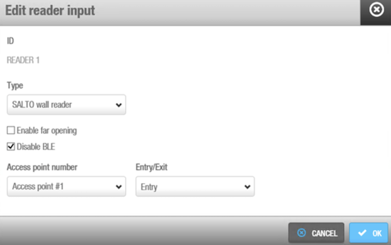 'Option um 'Eingänge des Lesers zu bearbeiten'
Die Felder für die Leser-Eingänge werden in der folgenden Tabelle angezeigt:
| Feld | Funktion |
|---|---|
| Typ | Sie können Keine auswählen, wenn kein Wandleser angeschlossen ist, oder Salto Wandleser, wenn es sich um einen Salto Wandleser handelt. Unabhängig von dieser Auswahl können die Eingänge 3 und 4, sowie 5 und 6 bei Bedarf weiterhin für Fremdleser konfiguriert werden. |
| Max. Lesefeld (BLE) aktiviert | Ermöglicht Ihnen Wandleser mit Fernöffnungen zu bedienen. Standardmäßig funktionieren Wandleser in neuen Datenbanken mit der Nahbereichsöffnung. Mit dieser Einstellung können Sie die Wandleser in die Fernöffnung setzen. Um diese Funktion nutzen zu können, aktualisieren Sie die Firmware auf die neueste Version. |
| BLE deaktivieren | Ermöglicht das Deaktivieren von JustIN Mobile Bluetooth LE-Schlüsseln. Diese können vom Wandleser dann nicht mehr gelesen werden. |
| Nummer des Zutrittspunkts | Da der CU4200 bis zu zwei verschiedene Zutrittspunkte verwalten kann, können Sie hier festlegen, ob der Leser eine Öffnung an Zutrittspunkt #1 oder #2 auslösen soll. Weitere Informationen finden Sie unter CU4200 (Erweiterung). |
| Eingang/Ausgang | Legt fest, ob der Wandleser als Eingang oder Ausgang arbeiten soll. |
Der CU4200 (Erweiterung) kann Eingänge von Fremdgeräten verwalten. Abhängig vom Signal oder den am Eingang angekommenen Daten verhält sich die CU4200 (Erweiterung) entsprechend. Wählen Sie die ID des Eingangs und klicken Sie auf Bearbeiten.
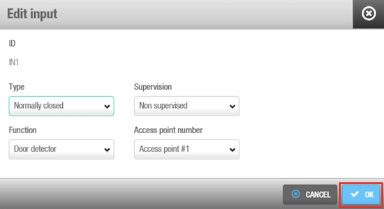 'Eingang bearbeiten'-Option
Die Felder Eingänge werden in der folgenden Tabelle beschrieben:
Felder für Eingänge: Typ
| Feld | Funktion |
|---|---|
| Schließer (NO) | Status of the relay in normal position. The relay will be opened in normal position. Dieser Typ ist für alle Eingänge von IN1 bis IN6 verfügbar |
| Öffner (NC) | Status of the relay in normal position. The relay will be closed in normal position. Dieser Typ ist für alle Eingänge von IN1 bis IN6 verfügbar |
| Fremdleser | Anstelle eines Salto Wandlesers, kann auch ein Fremdleser verwendet werden. Der Fremdleser benötigt 2 aufeinander folgende Eingänge: IN3 und IN4 oder IN5 und IN6. Fremdleser arbeiten mit einem Authentifikationscode, der im Profil der einzelnen Personen eingegeben werden muss. Siehe Personen erstellen für weitere Informationen, wie Authentifikationscodes in Personenprofilen eingegeben werden. |
| CUADAP | CU4200 können Daten von Medien an Drittanbieter-Anwendungen senden. Selecting CUADAP the CU will send the cardholder's Wiegang code in a Wiegand interface. Der CUADAP benötigt 2 aufeinander folgende Eingänge: IN3 und IN4 oder IN5 und IN6. See Creating Users for more information about how to enter a Wiegand code in the user profile. |
Felder für Eingänge: Überwachung
| Feld | Funktion |
|---|---|
| Überwachung | Wählen Sie den Widerstand, der für die Überwachung erforderlich ist. Überwachte Eingänge sind vor externen Angriffen geschützt. |
Felder für Eingänge: Funktion
| Feld | Funktion |
|---|---|
| Funktion | Select the function you want for the relay. Zu den Optionen gehören Türkontakt, Office-Aktivierung, Einbruchhemmung, Anforderung zum Öffnen oder Schließen eines Rolllos, Eingang oder Ausgang anfordern, Bitte nicht stören, Leser sperren, Alarmeingang, rotes und grünes Signal, Notschließung und -öffnung. Die Funktionen sind deaktiviert, wenn als Typ Fremdleser oder CUADAP ausgewählt wurde. |
Unter diesen Funktionen finden Sie Notschließung und Notöffnung. Dabei handelt es sich um zwei physische Eingänge der Steuerung, die es Benutzern ermöglichen, Notöffnungen oder -schließungen manuell direkt über die Hardware auszulösen. Diese physischen Eingänge ermöglichen die gleiche Funktionalität, die auch über die Software-Schnittstelle im Abschnitt Online-Überwachung > Zutrittspunkte verwendet werden kann.
For example, as demonstrated in the below screenshot, a relay in normally opened position could send a request to open a roller blind when presenting a valid key in reader #1 from IN1 and request to close the roller blind from IN2.
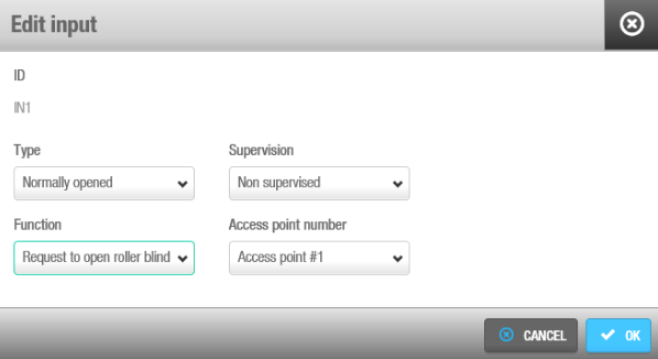 Beispielkonfiguration für Rollo
Nicht-Salto-Leser
Nicht-Salto-Leser können auch mit CU42xx-Steuerungen verwendet werden. Dafür müssen Sie zwei verschiedene Konzepte verstehen:
Wandleser-Konfiguration: Sie können den Eingangstyp des Lesers bearbeiten und auf Keine setzen, wenn Sie keinen der beiden verfügbaren Salto-Wandleser-Eingänge verwenden möchten. Dies ist nützlich, wenn Sie nur einen Salto-Leser anstelle von zweien benötigen.
Integration von Fremdlesern: Unabhängig davon können Sie Fremdleser an die Eingänge 3-6 anschließen. Dies funktioniert unabhängig von der Konfiguration Ihrer Salto Wandleser – Sie können beide, einen oder keinen Salto Wandleser aktivieren.
Diese flexible Konfiguration ermöglicht Szenarien, in denen beispielsweise ein Salto Wandleser den Zugang zum Büro steuert, während gleichzeitig ein Fremdleser (angebunden an dieselbe Steuerung) für eine Parkplatz-Schranke verwendet wird, die Kennzeichen liest.
Das Feld Typ unter Eingang bearbeiten zeigt die Option Fremdleser im Dropdown-Menü für IN3 und IN5 an. Es wird nur ein Wiegand-Code unterstützt. Weitere Informationen zum Konfigurieren des Wiegand-Formats finden Sie unter Konfigurieren von Wiegand-Codes.
An authorization code has to be entered for each user in the Authorization code field on the User profile. Weitere Informationen finden Sie im Abschnitt Benutzer. Wählen Sie den Zutrittspunkt aus dem Dropdown-Menü Nummer des Zutrittspunkts aus. Legen Sie außerdem fest, ob es sich um einen Eingang oder einen Ausgang handelt.
CUADAP
Bei Verwendung von CU4000 können Sie CUADAP-Einstellungen direkt über Space konfigurieren, da das CUADAP-Modul in die CU-Nodes integriert ist. Beachten Sie jedoch, dass die Einstellungen für CU5000-Geräte über die Hardware (DIP-Schalter) konfiguriert werden, die sich an der Steuerung selbst befinden.
In der Software müssen drei verschiedene Parameter festgelegt werden, um den CUADAP einzustellen. Diese Einstellungen finden Sie im CU4200 Node-Fenster unter System > Salto Netzwerk. Siehe auch So konfigurieren Sie die Steuerungen CU42E0 (Main) und CU420 (Erweiterung).
Einstellung 1
Definieren Sie zuerst den Eingang (3 oder 5) im Menü Typ, an den die Hardware des Drittanbieters angeschlossen wird. Die Software weist automatisch dem nächsten folgenden Eingang dieselbe Funktion zu, wie im folgenden Screenshot dargestellt:
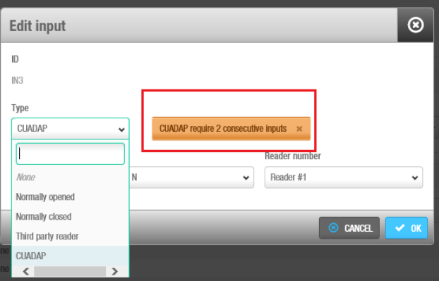 Typauswahl CUADAP
Einstellung 2
Der zweite Parameter legt fest, welcher Leser (Leser #1, Leser #2 oder beide), die Daten liest, die über den CUADAP an die Fremdhardware übertragen werden.
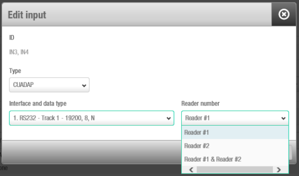 Dem CUADAP zugeordnete Leser-Nummer
Einstellung 3
Im dritten Parameter wählen Sie die Schnittstelle und den Datentyp aus. Denken Sie daran, dass die Daten, die während der Kodierung der Medien geschrieben werden sollen (Spurdaten und Wiegand), im Vorfeld in der Software einrichtet werden müssen. Siehe Personen erstellen für Informationen zur Verwendung von Spurdaten und Wiegand-Codes für Personen.
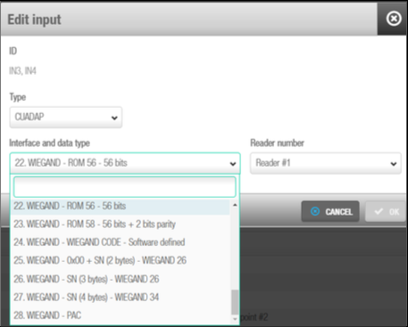 Auswahl von Schnittstelle und Datentyp
Die folgende Tabelle zeigt die verschiedenen Daten, Schnittstellen und Formate, die in Space verfügbar sind:
| Nummer | Daten | Schnittstelle | Format |
|---|---|---|---|
| 1 | Spur1 | RS232 (19200-8-N) | (STX, ETX, LRC) |
| 2 | Spur2 | RS232 (19200-8-N) | (STX, ETX, LRC) |
| 3 | Spur3 | RS232 (19200-8-N) | (STX, ETX, LRC) |
| 4 | % + ROM14 + ? | RS232 (19200-8-N) | RS232 (9600-8-N) |
| 5 | Spur1 | RS232 (9600-8-N) | PLAIN |
| 6 | Spur2 | RS232 (9600-8-N) | PLAIN |
| 7 | Spur3 | RS232 (9600-8-N) | PLAIN |
| 8 | % + ROM14 + ? | RS232 (9600-8-N) | PLAIN |
| 9 | Spur 1 | RS232 (19200-8-N) | PLAIN |
| 10 | Spur 2 | RS232 (19200-8-N) | PLAIN |
| 11 | Spur 3 | RS232 (19200-8-N) | PLAIN |
| 12 | ROM14 | RS232 (19200-8) | PLAIN |
| 13 | Spur1 | OMRON | BCD oder ALPHA |
| 14 | Spur2 | OMRON | BCD oder ALPHA |
| 15 | Spur2 | OMRON | BCD oder ALPHA (keine Nullen am Ende) |
| 16 | Spur3 | OMRON | BCD oder ALPHA |
| 17 | % + ROM14 + ? | OMRON | ALPHA |
| 18 | Spur1 | WIEGAND | BCD oder ALPHA |
| 19 | Spur2 | WIEGAND | BCD oder ALPHA |
| 20 | Spur3 | WIEGAND | BCD oder ALPHA |
| 21 | % + ROM14 + ? | WIEGAND | ALPHA |
| 22 | ROM | WIEGAND | 56-bit |
| 23 | ROM | WIEGAND | 56-Bit + 2 Paritätsbits |
| 24 | WIEGAND-CODE | WIEGAND | Format festgelegt in Space |
| 25 | 0X00+SN(2 Bytes) | WIEGAND | Standard 26-Bit |
| 26 | SN(3 Bytes) | WIEGAND | Standard 26-Bit |
| 27 | SN(4 Bytes) | WIEGAND | 32-Bit + 2 Paritätsbits |
Relais
Ein Relais ist ein elektrisch betätigter Schalter. Es wird dort eingesetzt, wo es notwendig ist, einen Stromkreis über ein Signal mit geringer Leistung zu steuern. For example, you can use relays to control an electric or magnetic strike, trigger a camera recording or turn an alarm off.
Der CU4200 (Erweiterung) verfügt über 4 Relais, die unabhängig voneinander konfiguriert werden können. Wählen Sie die Relais-ID aus und klicken Sie auf Bearbeiten.
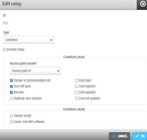 Relais bearbeiten
Die Felder Relais bearbeiten werden in der folgenden Tabelle beschrieben:
| Feld | Funktion |
|---|---|
| Typ | Wählen Sie den benötigten Typ aus. Weitere Informationen zu den verschiedenen Typen und Modi finden Sie in der untenstehenden Tabelle. |
| Nummer des Zutrittspunkts | Wählen Sie den gewünschten Zutrittspunkt. Es stehen Zutrittspunkt #1, Zutrittspunkt #2 oder beide zur Auswahl. |
| Schaltausgang | The Output drop-down menu is shown when Output is selected in the Type drop-down menu. Wählen Sie den Schaltausgang im Dropdown-Menü aus. Damit in der Liste Schaltausgänge angezeigt werden, müssen diese zuerst unter Zutrittspunkte > **Schaltausgänge erstellt werden. Weitere Informationen zum Erstellen von Schaltausgängen finden Sie unter Zutrittspunkte > Schaltausgänge. Das Relais wird ausgelöst, wenn ein Medium mit gültigen Schaltausgang-Berechtigungen am Wandleser präsentiert wird. Siehe Abschnitt zu Personen und Schaltaugängen für weitere Informationen darüber, wie man Personen Berechtigungen auf Schaltausgänge erteilt. |
| Checkbox Invertierte Relais | Die Option für invertierte Relais / ausfallsicheren Betrieb bewirkt, dass ein bestimmtes Relais im ausfallsicheren Modus arbeitet: Die Relais bleiben normalerweise eingeschaltet und schalten sich aus, wenn eine Aktivierung erforderlich ist. Diese Funktion basiert auf dem Austausch des Öffner (NC)-Schließer (NO)-Zustands des Relais, abhängig davon, ob die CU mit Strom versorgt wird oder nicht. Auf diese Weise unterscheidet sich der Ruhezustand der CU, wenn ein Problem mit der Stromversorgung des Geräts vorliegt. Der Modus ist für Fälle konzipiert, in der Personen Türen ohne Strom entriegeln müssen. |
Die folgende Tabelle beschreibt, wann die Relais 1 bis 4 ausgelöst werden. Wenn einer Person Zutritt gewährt wird, werden die Relais, wie in der folgenden Tabelle beschrieben, schalten. Relais können Öffner (NC, normally closed) oder Schließer (NO, normally opened) sein.
| Feld | Funktion |
|---|---|
| Karte akzeptiert | Das Relais schaltet, wenn ein gültiges Medium präsentiert wird. Zutrittspunkt #1, #2 oder beide können verwendet werden. |
| Rollo öffnen | Das Relais wird abwechselnd mit dem Relaistyp Rollo schließen ausgelöst, um ein Rollo zu öffnen. Wenn ein Relais als Rollo öffnen eingestellt ist, muss ein weiteres Relais als Rollo schließen eingestellt werden. Zutrittspunkt #1, #2 oder beide können verwendet werden. Hinweis: Wenn eine Tür als Rollo und ein Relais als Karte akzeptiert eingestellt ist, funktioniert die Tür wie im Toggle-Modus. |
| Rollo schließen | Das Relais wird abwechselnd mit dem Relaistyp Rollo öffnen ausgelöst, um ein Rollo zu schließen. Wenn ein Relais als Rollo schließen eingestellt ist, muss ein weiteres Relais als Rollo öffnen eingestellt werden. Zutrittspunkt #1, #2 oder beide können verwendet werden. Hinweis: Wenn eine Tür als Rollo und ein Relais als Karte akzeptiert eingestellt ist, funktioniert die Tür wie im Toggle-Modus. |
| Schaltausgang | Das Relais wird ausgelöst, wenn sich ein bestimmter Schaltausgang unter den Berechtigungen eines Mediums befindet. Wenn Sie diesen Typ auswählen, wird das Dropdown-Menü Schaltausgang angezeigt, sodass Sie den Schaltausgang auswählen können. Zutrittspunkt #1, #2 oder beide können verwendet werden. |
| Zeitgeber | Das Relais wird automatisch entsprechend einer eingestellten Zeitperiode ausgelöst. Wenn Sie diesen Typ auswählen, wird das Dropdown-Menü „Zeitperiode“ angezeigt, sodass Sie die benötigte Zeitperiode auswählen können. |
| Zeitgeber und Schaltausgang | Das Relais wird automatisch gemäß einer Zeitperiode oder nach Präsentieren eines berechtigten Mediums geschaltet, je nachdem, was zuerst eintritt. Wenn Sie diesen Typ auswählen, wird das Dropdown-Menü Schaltausgang angezeigt, sodass Sie den Schaltausgang auswählen können. Das Dropdown-Menü Zeitperiode wird ebenfalls angezeigt, sodass Sie die benötigte Zeitperiode auswählen können. Zutrittspunkt #1, #2 oder beide können verwendet werden. |
| Sabotage | Das Relais wird ausgelöst, wenn an einem Wandleser ein Sabotagealarm auftritt. Dies tritt auf, wenn ein Leser entfernt wird oder wenn die Kommunikation zur Steuerung abbricht. Zutrittspunkt #1, #2 oder beide können verwendet werden. |
| Tür zu lange offen | Das Relais wird ausgelöst, wenn die Tür zu lange offen gelassen wird. Wählen Sie unter Nummer des Zutrittspunkts einen Zutrittspunkt aus, der mit einem Türkontakt ausgerüstet ist. Zutrittspunkt #1, #2 oder beide können verwendet werden. |
| Einbruch | The relay will be triggered when an intrusion occurs at an access point. Zutrittspunkt #1, #2 oder beide können verwendet werden. |
| Duplizierter Türkontakt | The relay will be triggered to replicate the door detector alert. Dieser Modus kann verwendet werden, um ein Signal an eine andere Anwendung zu senden, wenn die Tür geöffnet wurde. |
| Medium gelesen | Das Relais schaltet kurz, nachdem ein Medium gelesen wurde. |
| Medium abgelehnt | Das Relais schaltet kurz, nachdem ein Medium abgelehnt wurde. |
| Medium aktualisiert | Das Relais schaltet kurz, nachdem ein Medium aktualisiert wurde. |
| Medium nicht aktualisiert | Das Relais schaltet kurz, wenn ein Medium nicht aktualisiert wurde. |
| Kombination | Das Relais wird entsprechend einer Kombination von Bedingungen geschaltet. So wird beispielsweise im oben dargestellten Screenshot "Relais bearbeiten" das Relais geschaltet, wenn Zutrittspunkt #1 zu lange offen gelassen wurde, wenn es einen Einbruchsalarm gibt oder wenn die Karte abgelehnt wird. Zutrittspunkt #1, #2 oder beide können verwendet werden. |
Initialisierung und Aktualisierung von Steuerungen
CU42E0 (Main) und CU4200 (Erweiterung) Geräte werden automatisch initialisiert und aktualisiert. In der folgenden Tabelle finden Sie die Häufigkeit der einzelnen Aktualisierungen.
| Automatischer Prozess | Frequenz der Überprüfung | Hinweise |
|---|---|---|
| CU42E0 (Main) Initialisierung der Türen | 1 Minute | Enthält Initialisierung + Update |
| CU42E0 (Main) Aktualisierung der Türen | 5 Minuten | Kann auf Anfrage ausgelöst werden |
| CU4200 (Erweiterung) Initialisierung | 1 Minute | Enthält Initialisierung + Update |
| CCU4200 (Auxiliary) update | 5 Minuten | Kann auf Anfrage ausgelöst werden |
Auch wenn Aktualisierungen für die Steuerungen automatisch alle 5 Minuten durchgeführt werden, kann eine manuelle Aktualisierung jederzeit erfolgen. Dazu müssen Sie das Gerät im Salto Netzwerk auswählen und dann auf Update klicken.
UBOX4000 (Updater)
UBOX4000-Updater sind CUs, die über ein Netzwerkkabel mit einem LAN (Local Area Network) verbunden sind. Sie verbinden sich mit dem Salto Netzwerk über eine TCP/IP-Verbindung. Die Funktionen des UBOX4000-Updaters beziehen sich hauptsächlich auf Aktualisierungsaufgaben und die Integration von Drittanbietern. Dieses Gerät unterstützt auch eine interne UBOX4000 (Erweiterung).
Die UBOX4000-Updater stellen eine Verbindung zwischen der Drittanbieter-Einheit und Space her und übertragen Daten an die Drittanbieter-Einheit. Das bedeutet, dass die externe Einheit keine TCP/IP-Verbindung benötigt. Sie müssen die Drittanbieter-Einheit über ein RS485-Kabel physisch mit einem UBOX4000-Updater verbinden, wodurch die Kommunikation zwischen ihnen hergestellt wird.
Führen Sie folgende Schritte aus, um einen UBOX4000-Updater hinzuzufügen:
Gehen Sie auf System > Salto Netzwerk. Das Salto Netzwerk wird angezeigt.
Klicken Sie auf Zufügen. Der Dialog zum Zufügen von Netzwerkgeräten wird angezeigt.
Wählen Sie in der Dropdown-Liste den Eintrag UBOX4000 (Updater) aus.
Klicken Sie auf OK. Das Informationsfenster UBOX4000 (Updater) wird angezeigt.
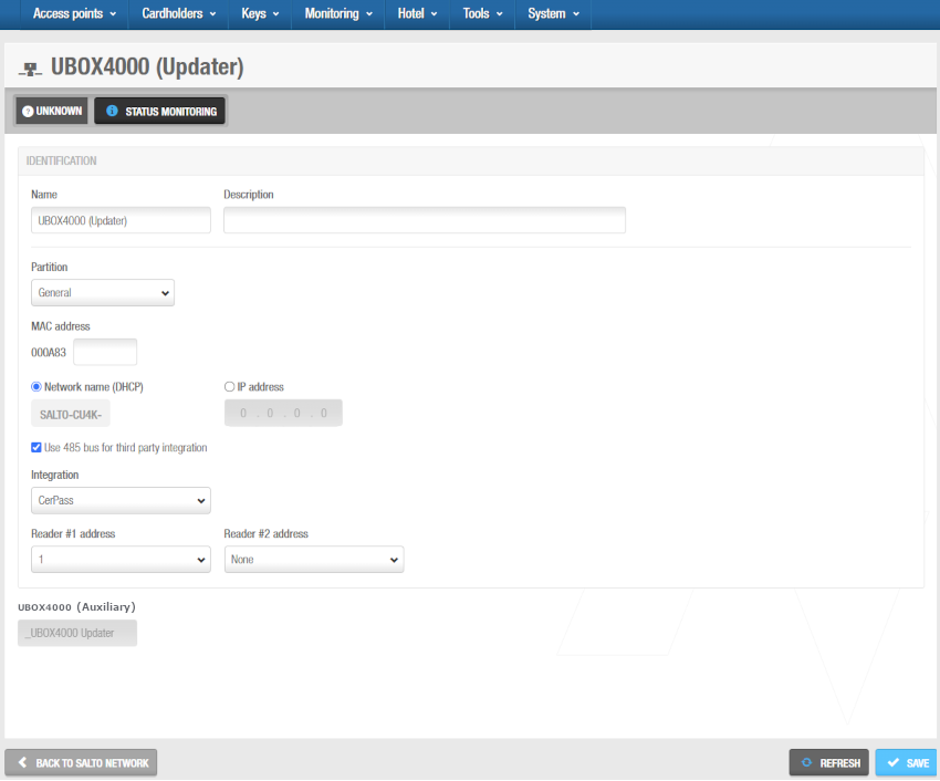 'UBOX4000 (Updater)' Info-Fenster
Geben Sie im Feld Name einen Namen für den UBOX4000-Updater ein.
Geben Sie im Feld Beschreibung eine Beschreibung für den UBOX4000-Updater ein. So können Sie beispielsweise beschreiben, wo sich der UBOX4000-Updater befindet.
Geben Sie im Feld MAC-Adresse die MAC-Adresse ein. Die MAC-Adresse befindet sich auf einem Aufkleber am UBOX4000-Updater.
Wählen Sie entweder die Option Netzwerkname (DHCP) oder IP-Adresse aus. Wenn Sie die Option Netzwerkname (DHCP) auswählen, wird dem UBOX4000-Updater automatisch eine IP-Adresse zugewiesen. Für diese Option sind ein DHCP-Server und ein DNS erforderlich. Wenn Sie die IP-Adresse Option auswählen, müssen Sie eine statische IP-Adresse im Feld eingeben.
Wählen Sie 485-Bus für Drittanbieterintegration verwenden, wenn das CerPass/OSDP-Protokoll für die Integration mit der entsprechenden Drittanbieterkomponente verwendet werden soll, die den RS485-Bus steuert. Sie können festlegen, welche Leser die empfangenen Daten von CerPass/OSDP senden. So können auch Leser verwendet werden, die nicht in der Integration genutzt werden sollen.
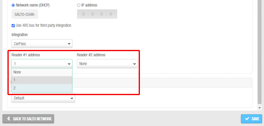 Leseradressen beim Senden der empfangenen Informationen per CerPass-Protokoll
Legen Sie die passende Zeitzone im gleichnamigen Auswahlfeld fest. Das Auswahlfeld Zeitzone wird Ihnen nur angezeigt, wenn Sie in den allgemeinen Optionen die Funktion zur Nutzung mehrerer Zeitzonen aktiviert haben. Siehe Mehrere Zeitzonen verwenden und Zeitzonen für weitere Informationen.
Klicken Sie auf Speichern. Die interne UBOX4000 (Erweiterung)-Steuerung wird im Abschnitt Zeitzone angezeigt. Weitere Informationen finden Sie unter UBOX4000 (Erweiterung)-Steuerungen.
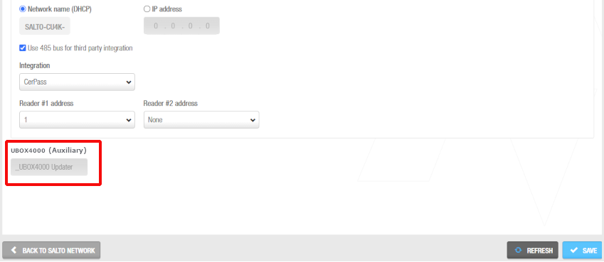 UBOX4000 (Erweiterung)
Wenn Sie eine UBOX4000 (Updater)-Steuerung hinzufügen, wird automatisch eine interne UBOX4000 (Erweiterung)-Steuerung erstellt. Diese kann nicht gelöscht werden. Jeder UBOX4000 (Updater) kann seine interne UBOX4000 (Erweiterung)-Steuerung und eine Integrationseinheit eines Drittanbieters unterstützen. Der Name der internen UBOX4000 (Erweiterung)-Steuerung ist immer der gleiche wie der des übergeordneten UBOX4000 (Updater), dem ein Unterstrich vorangestellt ist. Zum Beispiel: _UBOX4000-Updater.
- Klicken Sie auf Zurück zum Salto Netzwerk, um zum Salto Netzwerk zurückzukehren.
UBOX4000 (Erweiterung)
UBOX4000 (Erweiterung)-Steuerungen sind Netzwerkverbindungspunkte, die Teil eines UBOX4000 (Updater) sind.
Sie müssen UBOX4000 (Erweiterung)-Steuerungen mit einem Zutrittspunkt verbinden, damit das System anzeigen kann, welche Elemente verbunden sind.
Wenn Sie eine UBOX4000 (Updater) erstellen, wird automatisch eine interne UBOX4000 (Erweiterung)-Steuerung erstellt. Sie können jedoch seine Konfiguration ändern.
Um die Konfiguration der internen UBOX4000 (Erweiterung)-Steuerung zu ändern, gehen Sie wie folgt vor:
Gehen Sie auf System > Salto Netzwerk. Das Salto Netzwerk wird angezeigt.
Klicken Sie auf die zu ändernde UBOX4000 (Erweiterung)-Steuerung. Der Informationsbildschirm UBOX4000 (Erweiterung) wird angezeigt.
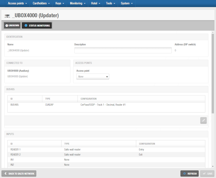 'UBOX4000 (Updater)' Info-Bildschirm
Nehmen Sie die erforderlichen Änderungen in den Bereichen Bus485, Relais und Eingänge vor, indem Sie den entsprechenden Bus485/Relais/Eingang auswählen und auf die Schaltfläche Bearbeiten (Stiftsymbol) klicken.
Speichern Sie die Änderungen und klicken Sie dann auf Zurück zu Salto Netzwerk, um zum Bildschirm Salto Netzwerk zurückzukehren.
GC7 (Gantner)
In früheren Versionen von Space werden die Bezeichnungen "Gantner Controller" und "GAT Net Controller" anstelle von GC7 (Gantner)-Controllern verwendet.
GC7 (Gantner)-Controller sind netzwerkgebundene Hardwaregeräte, mit denen der Zugriff auf Online-GAT Net-Schließfächer gesteuert werden kann. Siehe Verbindungstypen für weitere Informationen über diese Art von Lockern.
Um einen GC7 (Gantner)-Controller hinzuzufügen, gehen Sie wie folgt vor:
Gehen Sie auf System > Salto Netzwerk. Das Salto Netzwerk wird angezeigt.
Klicken Sie auf Zufügen. Der Dialog zum Zufügen von Netzwerkgeräten wird angezeigt.
Wählen Sie GC7 (Gantner) aus der Dropdown-Liste aus.
Klicken Sie auf OK. Der Informationsbildschirm GC7 (Gantner) wird angezeigt.
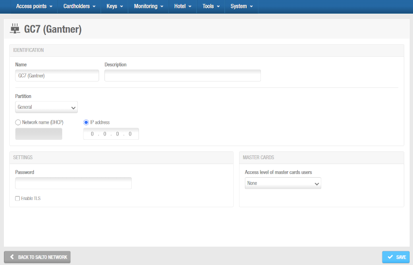 'GC7 (Gantner)' Info-Bildschirm
Geben Sie im Feld Name einen Namen für den GC7 (Gantner)-Controller ein.
Geben Sie im Feld Beschreibung eine Beschreibung für den GC7 (Gantner)-Controller ein. Sie kann beispielsweise verwendet werden, um zu beschreiben, wo sich der GC7 (Gantner)-Controller befindet.
Wählen Sie bei Bedarf die Partition aus der Dropdown-Liste Partition aus. SiehePartitionen für weitere Informationen.
Beachten Sie, dass die Funktion Partitionen lizenzabhängig sind. Siehe Space registrieren und lizenzieren für weitere Informationen.
Wählen Sie entweder die Option Netzwerkname(DHCP) oder IP-Adresse aus. Wenn Sie die Option Netzwerkname (DHCP) wählen, wird dem GC7 (Gantner)-Controller automatisch eine IP-Adresse zugewiesen. Für diese Option sind ein DHCP-Server und ein DNS erforderlich. Wenn Sie die IP-Adresse Option auswählen, müssen Sie eine statische IP-Adresse im Feld eingeben.
Geben Sie im Abschnitt Einstellungen das Passwort ein, das Sie bei der Konfiguration des G7-Controllers im G7 Web Interface definiert haben, und aktivieren Sie bei Bedarf die Option TLS aktivieren. Diese Option ermöglicht die verschlüsselte Kommunikation zwischen dem Controller und Space. Wenn Sie diese Option auswählen, müssen Sie im Controller ein Zertifikat konfigurieren.
Informieren Sie sich in der Salto PartnerArea oder kontaktieren Sie Ihren Salto-Vertreter, um weitere Informationen über die G7-Einrichtung für GAT. NET Locker in Space zu erhalten.
- Legen Sie im Abschnitt Masterkarten fest, welche Personengruppe für Masterkarten Sie für diesen Controller verwenden wollen. Bei Masterkarten handelt es sich um Medien, die Locker jederzeit öffnen können, bspw. zu Wartungszwecken. GAT NET Locker ermöglichen die Funktion von Masterkarten auch im Offline-Fall(keine Verbindung zum Host). Masterkarten werden auf dem G7-Controller gespeichert. Es sind maximal 10 Karten pro Controller möglich. Beachten Sie, dass es auch eine andere Art von Masterkarte namens "Service-Masterkarte" gibt. Dieser Typ von Masterkarte funktioniert, wenn das System online ist.
Informieren Sie sich in der Salto PartnerArea oder kontaktieren Sie Ihren Salto-Vertreter, um weitere Informationen über die Einrichtung für GAT. NET Locker in Space zu erhalten.
Als Beispiel für das Erstellen einer Masterkartenliste sollten Sie eine Personengruppe erstellen und diese wie folgt konfigurieren: Medien werden GAT-Net-Locker-Masterkarten sein. Anschließend sollten Sie bei der Konfiguration des GAT Net-Locker-Bereichs die Option Ist ein GAT Net-Locker-Bereich aktivieren, die Locker in diesen Bereich einfügen und festlegen, für welche GC7 (Gantner)-Controller diese Personengruppe der Master ist. Weitere Informationen finden Sie unter Bereiche.
- Speichern Sie die Änderungen. Der Abschnitt Locker wird auf der rechten Seite des Bildschirms angezeigt. Dort können Sie Locker mit Verbindung zu diesem Controller zufügen(+) oder löschen(-). Sie können dort auch die Werte des Subcontrollers anpassen, indem Sie auf das Stift-Symbol klicken.
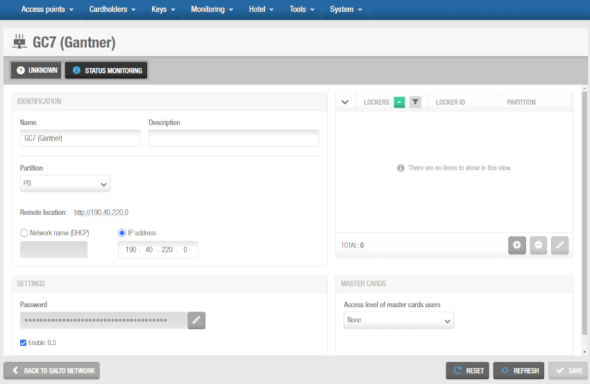 GC7 (Gantner)-Controller und GAT Net-Locker verbinden
Wenn Sie auf Zufügen(+) klicken, wird ein Dialog angezeigt, der alle GAT Net Locker auflistet, die bereits zum System zugefügt wurden. Weitere Informationen zum Hinzufügen von GAT Net Lockern zu Space finden Sie im Abschnitt Locker. Wählen Sie die Locker aus die Sie verbinden möchten und speichern Sie. Sie können keine Locker hinzufügen, die bereits zu einem anderen GC7 (Gantner)-Controller gehören. Sie können Online-GAT Net-Locker auch mit GC7 (Gantner)-Controllern verbinden, wenn Sie dem System Locker hinzufügen.
Die Buttons bearbeiten(Stift) und Löschen(-) sind nur aktiv, wenn Sie mindestens einen Locker ausgewählt haben.
- Klicken Sie auf Zurück zum Salto Netzwerk, um zum Salto Netzwerk zurückzukehren.
Funk-Hardware
Gateways sind Geräte, die eine Verbindung zwischen Netzwerken herstellen, die unterschiedliche Basisprotokolle verwenden. Sie können im Salto Netzwerk zwei Arten von Gateways zum System zufügen:
Gateway (RFnet/BLUEnet)
RFnet/BLUEnet-Gateways ermöglichen die Datenübertragung zwischen dem System und Funk-vernetzten Salto-Türkomponenten. RFnet/BLUEnet Gateways werden mit RFnet- und BLUEnet-Nodes verbunden. Siehe den Abschnitt RFnet/BLUEnet Nodes für weitere Informationen.
Je nach Art der Türkomponente unterstützt Space zwei verschiedene Funktechnologien: RFnet und BLUEnet. Das Ethernet-Verhalten des Gateways ist für diese beiden Technologien gleich. Aus diesem Grund ist die Gateway-Einstellung die gleiche. Was sich ändert, ist lediglich der interne Node (Antenne) des Gateways: Dieser unterstützt je nach Art der Türkomponenten RFnet oder BLUEnet.
Sie müssen RFnet/BLUEnet-Nodes über ein RS485-Kabel physisch mit einem Gateway verbinden, um die Kommunikation zwischen den externen Nodes und dem Gateway herzustellen.
Weitere Informationen finden Sie im Gateway-Datenblatt. Wenden Sie sich an Ihren Salto Partner oder den technischen Support, um eine Kopie dieses Dokuments anzufragen.
Sie müssen die Gateways und Nodes auch in Space verknüpfen, um festzulegen, welche Komponenten miteinander kommunizieren.
Gehen Sie wie folgt vor, um ein Gateway (RFnet/BLUEnet) hinzuzufügen:
Gehen Sie auf System > Salto Netzwerk. Das Salto Netzwerk wird angezeigt.
Klicken Sie auf Zufügen. Der Dialog zum Zufügen von Netzwerkgeräten wird angezeigt.
Wählen Sie Gateway (RFnet/BLUEnet) aus der Dropdown-Liste aus:
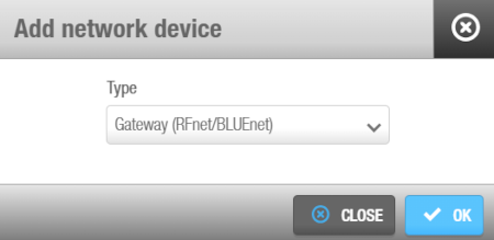 'Dialogfeld 'Netzwerkgerät hinzufügen'
Klicken Sie auf OK. Der Informationsbildschirm Gateway (RFnet/BLUEnet) wird angezeigt.
Geben Sie dem Gateway im entsprechenden Feld einen Namen.
Geben Sie im Feld Beschreibung eine Beschreibung für das Gateway ein. Dort könnte bspw. der Standort des Gateways vermerkt werden.
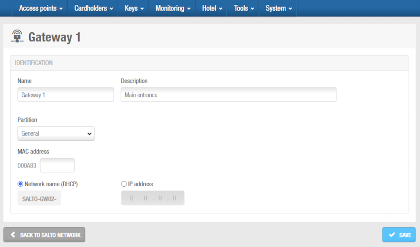 'Gateway (RFnet/BLUEnet)' Info-Bildschirm
Geben Sie die Media-Access-Control-Adresse(MAC) in das Feld MAC ein. Diese finden Sie auf einem Aufkleber am Encoder.
Wählen Sie entweder die Option Netzwerkname (DHCP) oder IP-Adresse aus.
- Wenn Sie die Option Netzwerkname (DHCP) wählen, wird dem Gateway (RFnet/BLUEnet) automatisch eine IP-Adresse zugewiesen. Für diese Option sind ein Dynamic-Host-Configuration-Protocol-Server(DHCP) und ein DNS erforderlich.
- Wenn Sie die IP-Adresse Option auswählen, müssen Sie eine statische IP-Adresse im Feld eingeben.
Legen Sie die passende Zeitzone im gleichnamigen Auswahlfeld fest. Das Auswahlfeld Zeitzone wird Ihnen nur angezeigt, wenn Sie unter System > allgemeine Optionen die Funktion zur Nutzung mehrerer Zeitzonen aktiviert haben. Siehe Mehrere Zeitzonen verwenden und Zeitzonen für weitere Informationen.
Klicken Sie auf Speichern. Das Fenster Nodes wird auf der rechten Seite des Bildschirms angezeigt. Dort können Sie Nodes mit Verbindung zu diesem Gateway zufügen(+) oder löschen(-).
Wenn Sie auf Zufügen(+) klicken, wird ein Dialog angezeigt, der alle Nodes auflistet, die bereits zum System zugefügt wurden. Wählen Sie die Nodes aus die Sie verbinden möchten und speichern Sie. Sie können keine Nodes verbinden, die schon mit einem anderen Gateway verbunden sind. Sie können RFnet/BLUEnet Nodes auch direkt bei Erstellung mit einem Gateway verbinden.
Um den Entfernen-Button(-) zu aktivieren, müssen Sie mindestens einen Node auswählen.
- Klicken Sie auf Zurück zum Salto Netzwerk, um zum Salto Netzwerk zurückzukehren.
Die Option Diagnose starten ermöglicht es, die Qualität der drahtlosen Kommunikation zwischen einem bestimmten Gateway (RFnet/BLUEnet) (und seinen Nodes) und den daran angeschlossenen Türkomponenten zu analysieren.
Das Gateway muss über aktuelle Firmware verfügen.
Wenden Sie sich an Ihren technischen Support, um detailliertere Informationen zu diesen Optionen zu erhalten.
Über diese Funktion können Sie Logs für jeden Gateway-Abschnitt erzeugen.
Die Logs werden als .txt Dateien im Salto Space Logs Ordner erstellt.
Beachten Sie, dass die Türkomponenten unter dem jeweiligen Gateway während dieses Tests nicht online sind. Abhängig von der Anzahl der Türkomponenten, kann dieser Test von 5 Minuten bis 1,5 Stunden dauern. Sie können diesen Test stoppen, indem Sie den Space-Dienst neu starten. Diese Diagnose kann zu Beginn der Konfiguration eines Funksystems durchgeführt werden, um die Signal-Qualität zu überprüfen oder festzustellen, ob ein Problem mit der drahtlosen Kommunikation in einem drahtlosen RFnet- oder BLUEnet-System vorliegt.
RFnet/BLUEnet Nodes
Nodes sind Netzwerkverbindungspunkte, die über ein RS485-Kabel physisch mit einem Gateway verbunden sind, wodurch die Kommunikation zwischen den Funk-Nodes und den Funk-Gateways hergestellt wird. In Space müssen Sie Funk-Nodes mit Funk-Gateways und Funk-Zutrittspunkte mit Funk-Nodes verbinden, damit das System anzeigen kann, welche Elemente verbunden sind. Es gibt zwei Arten von Funk-Nodes, die auf der Funkplattform basieren (RFnet oder BLUEnet). Gateways können beide Arten von Knoten gleichzeitig verwalten. Weitere Informationen finden Sie unter Gateway (RFnet/BLUEnet).
Sie müssen die entsprechende Online-Funk-Option im Fenster Verbindungstyp auf dem Informationsbildschirm Tür oder Zimmer auswählen, um eine Tür als Funk-Zutrittspunkt zu definieren. Siehe Verbindungstypen von Türen oder Verbindungstypen für Hotelzimmer.
So fügen Sie einen RFnet/BLUEnet Node hinzu:
Gehen Sie auf System > Salto Netzwerk. Das Salto Netzwerk wird angezeigt.
Klicken Sie auf Zufügen. Der Dialog zum Zufügen von Netzwerkgeräten wird angezeigt.
Wählen Sie aus der Dropdown-Liste entweder Node (RFnet) oder Node (BLUEnet) aus.
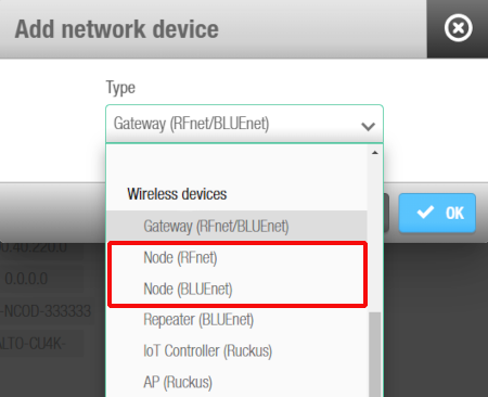 'Netzwerkgerät hinzufügen' Dialogfeld - 'Funk-Node' Dropdown-Liste
- Klicken Sie auf OK. Der Info-Bildschirm RF Node wird angezeigt.
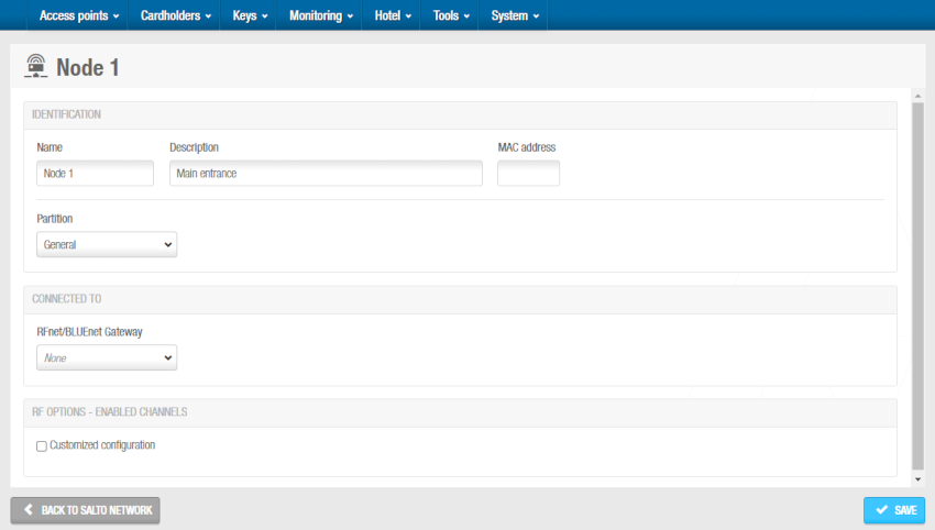 Info-Bildschirm 'Funk Node'
Geben Sie dem RF Node im entsprechenden Feld einen Namen.
Geben Sie im Feld Beschreibung eine Beschreibung für den Node ein. Dort könnte bspw. der Standort des Nodes vermerkt werden.
Geben Sie im Feld MAC-Adresse die MAC-Adresse ein.
Wählen Sie bei Bedarf die Partition aus der Dropdown-Liste Partition aus. SiehePartitionen für weitere Informationen.
Beachten Sie, dass die Funktion Partitionen lizenzabhängig ist. Siehe Space registrieren und lizenzieren für weitere Informationen.
Wählen Sie im Dropdown-Menü Verbunden mit das RF Gateway aus, mit dem Sie den RF Node verbinden möchten. Die Standard-Einstellung ist Keine.
Klicken Sie auf Speichern. Der Bereich BLUEnet-Zugtrittspunkte oder RFnet-Zutrittspunkte wird auf der rechten Seite des Bildschirms angezeigt. Der Bereich BLUEnet-Repeater wird ebenfalls angezeigt, falls zutreffend.
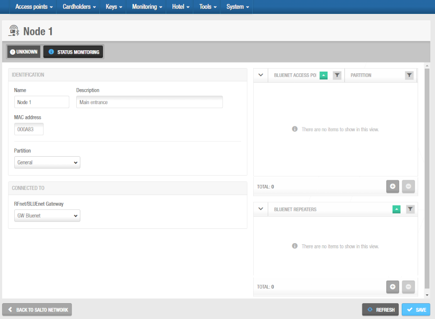 Abschnitte Zutrittspunkte und Repeater - Info-Bildschirm 'Funk-Node'
- Im Abschnitt Zutrittspunkte für RFnet oder BLUEnet können Sie Zutrittspunkte hinzufügen (+) und löschen (-), die mit diesem Funk-Node verbunden sein sollen.
Wenn Sie auf die Schaltfläche Hinzufügen (+) klicken, wird das Dialogfeld Hinzufügen angezeigt, das nur dann eine Liste der Funk-Zutrittspunkte enthält, wenn Sie bereits Türen als Funk-Zutrittspunkte festgelegt haben, indem Sie die entsprechende Online-Funk-Option im Bereich Verbindungstypen auf dem Informationsbildschirm Tür oder Zimmer ausgewählt haben. Wählen Sie die hinzuzufügenden Zutrittspunkte aus und speichern Sie die Änderungen. Sie können Online-Funk-Zutrittspunkte auch mit RF-Nodes verbinden, wenn Sie einen Zutrittspunkt erstellen. Weitere Informationen finden Sie unter Online RFnet. Sie können keine Funk-Zutrittspunkte hinzufügen, die bereits zu einem anderen Node gehören.
Um die Schaltfläche Löschen (-) zu aktivieren, wählen Sie den Zutrittspunkt aus, den Sie löschen möchten.
- Im Bereich BLUEnet-Repeater können Sie BLUEnet-Repeater hinzufügen (+) und löschen (-), die mit diesem Funk-Node verbunden werden sollen.
Wenn Sie auf die Schaltfläche Hinzufügen (+) klicken, wird das Dialogfeld Hinzufügen angezeigt, das nur dann eine Liste der BLUEnet-Repeater anzeigt, wenn Sie diese bereits zum System hinzugefügt haben. Wählen Sie die hinzuzufügenden Repeater aus und speichern Sie die Änderungen. Sie können BLUEnet-Repeater auch mit Funk-Nodes verbinden, wenn Sie einen Repeater zum System hinzufügen. Weitere Informationen finden Sie unter Online RFnet. Sie können keine BLUEnet-Repeater hinzufügen, die bereits zu einem anderen Node gehören.
Um die Schaltfläche Löschen (-) zu aktivieren, wählen Sie den Repeater aus, den Sie löschen möchten.
- Klicken Sie auf Zurück zum Salto Netzwerk, um zum Salto Netzwerk zurückzukehren.
Funk-Gateways haben einen Mini-Node, der mit ihnen verbunden ist. Sie müssen diesen Node in Space hinzufügen, indem Sie der Vorgehensweise zum Hinzufügen von Funk-Nodes folgen. Außerdem müssen Sie den Mini-Node in Space mit dem Funk-Gateway verbinden.
Repeater (BLUEnet)
BLUEnet-Repeater sind Geräte mit Netzwerkverbindungspunkten, die einem Node oder einem anderen Repeater zugeordnet sind und es ermöglichen, die Entfernung zwischen einem Gateway und einer elektronischen Türkomponente zu vergrößern. Der Salto BLUEnet-Repeater basiert auf der drahtlosen Salto BLUEnet-Kommunikation und muss nicht verkabelt werden.
Gehen Sie folgendermaßen vor, um einen BLUEnet-Repeater hinzuzufügen:
Gehen Sie auf System > Salto Netzwerk. Das Salto Netzwerk wird angezeigt.
Klicken Sie auf Zufügen. Der Dialog zum Zufügen von Netzwerkgeräten wird angezeigt.
Wählen Sie Repeater (BLUEnet) aus der Dropdown-Liste aus.
Klicken Sie auf OK. Der Informationsbildschirm Repeater (BLUEnet) wird angezeigt.
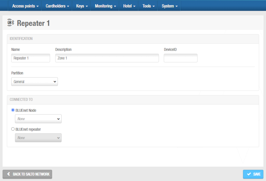 'Repeater (BLUEnet)' Info-Bildschirm
Geben Sie im Feld Name einen Namen für den BLUEnet-Repeater ein.
Geben Sie im Feld Beschreibung eine Beschreibung für den BLUEnet-Repeater ein. So kann beispielsweise beschrieben werden, wo sich der BLUEnet-Repeater befindet.
Geben Sie die Device-ID in das Feld DeviceID ein.
Wählen Sie bei Bedarf die Partition aus der Dropdown-Liste Partition aus. SiehePartitionen für weitere Informationen.
Beachten Sie, dass die Funktion Partitionen lizenzabhängig ist. Siehe Space registrieren und lizenzieren für weitere Informationen.
Wählen Sie in der Dropdown-Liste im Bereich Verbunden mit den BLUEnet-Node oder einen anderen BLUEnet-Repeater aus, mit dem Sie den BLUEnet-Repeater verbinden möchten. Die Standard-Einstellung ist Keine.
Klicken Sie auf Speichern. Die Bereiche BLUEnet-Zutrittspunkte und BLUEnet-Repeater werden auf der rechten Seite des Bildschirms angezeigt.
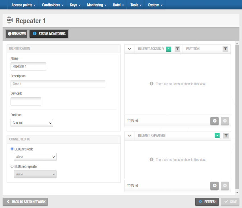 Abschnitte Zutrittspunkte und Repeater - Informationsbildschirm 'BLUEnet-Repeater'
- Im Abschnitt BLUEnet-Zutrittspunkte können Sie BLUEnet-Zutrittspunkte hinzufügen (+) und löschen (-), die mit diesem BLUEnet-Repeater verbunden werden sollen.
Wenn Sie auf die Schaltfläche Hinzufügen (+) klicken, wird das Dialogfeld Hinzufügen angezeigt, das nur dann eine Liste der BLUEnet-Zutrittspunkte enthält, wenn Sie bereits Türen als BLUEnet-Zutrittspunkte festgelegt haben, indem Sie die entsprechende BLUEnet-Option im Abschnitt Verbindungstypen auf dem Informationsbildschirm Tür oder Zimmer ausgewählt haben. Wählen Sie die hinzuzufügenden Zutrittspunkte aus und speichern Sie die Änderungen. Sie können BLUEnet-Zutrittspunkte auch mit BLUEnet-Repeatern verbinden, wenn Sie einen Zutrittspunkt erstellen. Sie können keine BLUEnet-Zutrittspunkte hinzufügen, die bereits zu einem anderen Repeater/Node gehören.
Um die Schaltfläche Löschen (-) zu aktivieren, wählen Sie den Zutrittspunkt aus, den Sie löschen möchten.
- Im Abschnitt BLUEnet-Repeater können Sie BLUEnet-Repeater hinzufügen (+) und löschen (-), die mit diesen BLUEnet-Repeatern verbunden werden sollen.
Wenn Sie auf die Schaltfläche Hinzufügen (+) klicken, wird das Dialogfeld Hinzufügen angezeigt, das nur dann eine Liste der BLUEnet-Repeater anzeigt, wenn Sie diese bereits zum System hinzugefügt haben. Wählen Sie die hinzuzufügenden Repeater aus und speichern Sie die Änderungen. Sie können BLUEnet-Repeater auch mit BLUEnet-Repeatern verbinden. Sie können keine BLUEnet-Repeater hinzufügen, die bereits zu einem anderen Repeater/Node gehören.
Um die Schaltfläche Löschen (-) zu aktivieren, wählen Sie den Repeater aus, den Sie löschen möchten.
- Klicken Sie auf Zurück zum Salto Netzwerk, um zum Salto Netzwerk zurückzukehren.

 Zurück
