Controllers in Homelok
Overview
Controllers are mains-wired hardware devices that can be used to control access where a standalone lock cannot be fitted. This could be, for example, on car park barriers, turnstiles, sliding doors or in elevators, in conjunction with the destinations feature.
Controllers used in Salto Homelok
The BLUEnet Controller is a specific type of controller used in Salto Homelok which is designed to be used where a larger more complex installation is not required. This model supports one reader device, but can be expanded with output expansion units and exit reader units to support multiple destinations and readers.
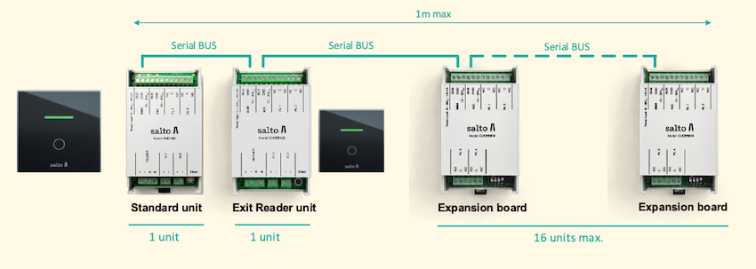 BLUEnet Controller architecture example
The destinations feature works with the BLUEnet Controller range of devices.
See also the BLUEnet Controller installation guide for more information.
Creating controllers
Before you can link destinations or doors to a controller, you must first create them in Homelok. To create a destination, go to Settings > Destinations. If you are using controllers in conjunction with doors, you must also create these doors separately in the Doors section. See also the sections on Destinations and Doors in the Homelok user guide for more information on how to create these.
In a similar way to electronic locks, you use either a door or destinations to manage the behavior of a controller within your installation's access plan. In this sense, a door in the Homelok system can represent the physical controller device.
You can create controllers in Homelok via the web interface or using the Nebula Commissioning app during the device configuration process. If you create controllers via the web interface, they still need to be configured using the app.
To configure a controller, it needs to be connected to a reader device, like a Design XS Reader.
For a full description of how to create and configure controllers see also the section on configuring devices in the Nebula installer documentation.
To create a controller go to the Devices section and click Create.
Ensure that in the Type field, Controller is selected. Give the controller a name and select the Connection type.
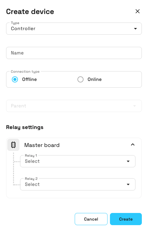 Creating a controller in Homelok web
Connection type
Controllers can either be online or offline.
Online
Online controllers in Homelok, like the BLUEnet Controller, are wirelessly connected to the internet. To connect to the internet, an online controller needs a parent device, like a gateway. If you're creating an online controller, select Online in the connection type.
If the controller is to be connected to a parent device, you need to add the name of that device. Selecting Online activates a pop-up Select parent device window with a list of previously created parent devices. Note that Parent device is an optional field.
It's recommended that you create the parent device in the Devices section before creating the controller that you want to associate with it.
Offline
Offline controllers are not connected to the Salto network and you need to update them using the Nebula Commissioning app if you want to make a change to them like a firmware update, for example. An offline controller does not need a parent device.
Although not as common as online controllers, some installations may use offline controllers where key data is not required to be updated at the door. i.e.: the controller is plugged in to the mains supply and connected to the door, for example, a sliding glass door, via a relay.
Relay settings
You use the relay settings section to manage the behavior of controllers within your installation's access plan. You can connect a relay to either a door or a destination, depending on how you want to use the controller.
A controller can manage either one door or multiple destinations, but not both simultaneously. Choosing a door disables the other relay assignments and expansion controls in Homelok web. Choose destination mode if you need to assign multiple destinations to the controller's relays. See the relay assignment logic section in the destinations guide for more detail on how this affects destinations.
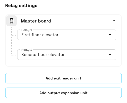 Relay settings option
These relay settings correspond to the relays on the physical controller device, marked on the physical device with RL 1 and RL 2.
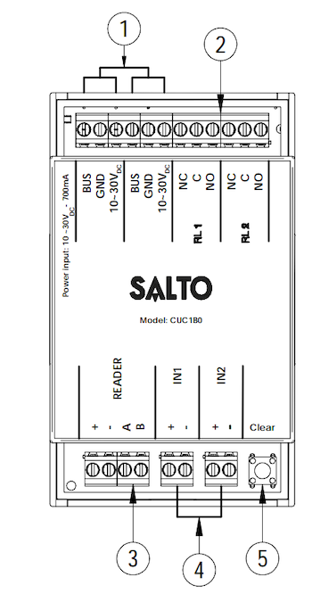 The BLUEnet Controller 2 relay outputs, marked here with the number '2'
Key
- Input/Output: power input/output and proprietary serial bus for communication with expansion units. There are two groups of connections that are 100% identical.
- Relay outputs: (1A/30VDC).
- Connection with the reader: consult the reader installation guides for more detailed information about the type of recommended wiring, connections and maximum distances.
- Inputs: inputs for external configuration (default, IN2, tamper).
- Clear button: short press (< 3 seconds) to pair with the connected wall reader and discover and pair devices on the proprietary serial bus.
To associate a relay with a door, select the Doors tab and then select the door you want to associate with the relay. To associate a relay with a destination, select the Destination tab and then select the destination you want to associate with the relay.
As noted above, this Doors/Destination choice applies to the whole controller. Door mode supports one door, while destination mode allows assignments across the controller's relays and output expansion units.
If you change the purpose of a controller from enabling destinations to doors or vice versa, you must reset and reconfigure the controller. Reconfiguring alone doesn't apply the change to the relays.
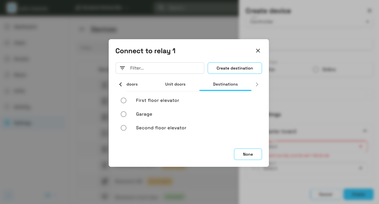 You can connect relays to installation and unit doors, or destinations
If you also have unit doors in your installation, these will display in the Connect to dropdown list.
Add output expansion units
For the BLUEnet Controller in destination mode, you can add output expansion units to increase the number of relays available, and exit reader units to add additional readers. Output expansion units let you control more than two destinations with a single controller, not additional doors. You can add up to 16 output expansion units, and each output expansion unit typically provides 4 additional relays.
The controller's master board and each output expansion unit or exit reader unit must be installed within 1 meter of each other, since they communicate over a serial bus.
See also the installation guide for the BLUEnet Controller Expansion Board for more information about expansion units.
Output expansion units and exit reader units are accessories added to an existing controller, not device types you create separately in the Devices section.
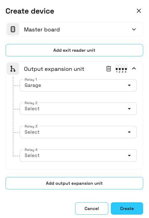 You can add up to 16 output expansion units, and each unit typically provides 4 additional relays
Adding extra units
To add an output expansion unit in destination mode, select the Add output expansion unit option in the relay settings section. You must have at least one physical output expansion unit device connected to the main controller to use this feature.
Installers need to physically configure DIP switches on the expansion boards sequentially (0000, 0001, 0010, 0011, etc.) as they are added. The DIP switches are numbered 1 to 4 below each switch for easy identification, matching the format shown in the installation guide.
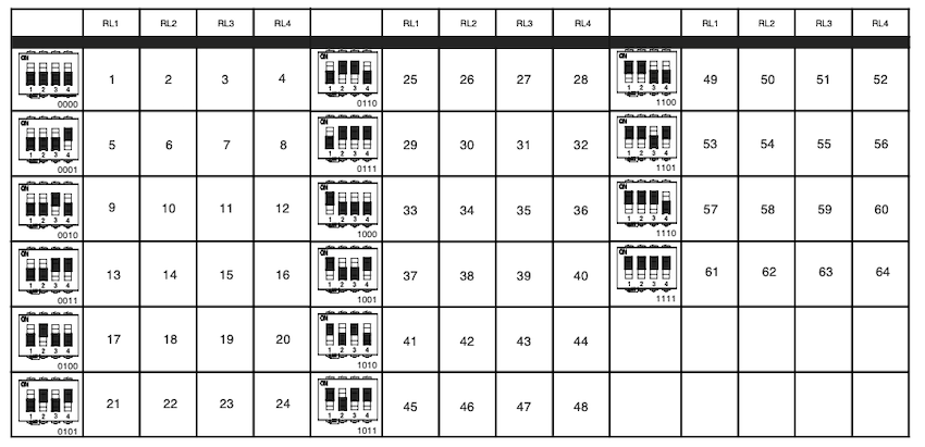 DIP switch configuration example showing switches numbered 1 to 4
Adding exit reader units
Exit reader units are not displayed by default under the main board configuration. In destination mode, you can add one by selecting the Add exit reader unit button when needed. This allows you to add additional reader points for more complex access control scenarios, enabling separate entry and exit control with a second wall reader.
Although an exit reader unit has its own relays, it doesn't provide an additional door or destination access point. A controller supports at most one exit reader unit, unlike output expansion units, of which you can add up to 16. Exit reader units don't have DIP switches, unlike output expansion units.
Once you have created and configured the controller, you can view or edit the configuration settings by clicking on the controller name in the Devices section.
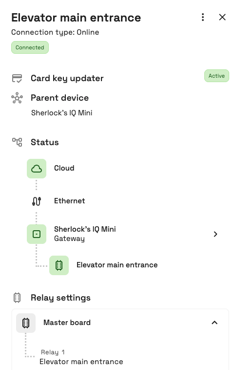 Click on the controller name to view or edit its configuration settings
Firmware
Once a controller has been configured by the Nebula Commissioning app, you can see the firmware number and version of the device in the Firmware section of the side panel.
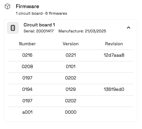 Example of how firmware numbers and versions are displayed
See also the section on updating firmware for more information about firmware updates.
Remote unlocking
Remote unlocking is a feature that allows you to unlock a door controlled by a controller device. This feature is only available for online controllers.
Remote unlocking for controllers works in the same way as it does for doors. See the section on remote unlocking for more information.
 Back
Back
